Toyota Corolla Cross: Removal
REMOVAL
CAUTION / NOTICE / HINT
COMPONENTS (REMOVAL)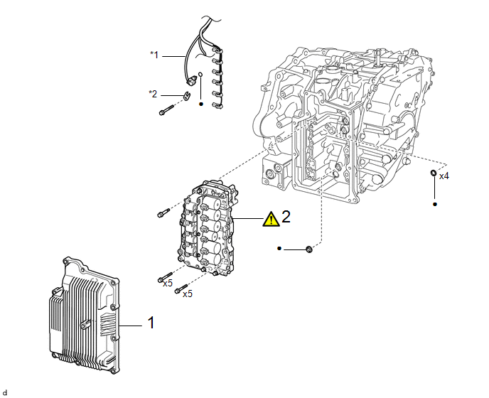
|
Procedure |
Part Name Code |
.png) |
.png) |
.png) |
|
|---|---|---|---|---|---|
|
1 |
TRANSAXLE SIDE COVER SUB-ASSEMBLY |
35015Y |
- |
- |
- |
|
2 |
TRANSMISSION VALVE BODY ASSEMBLY |
35410J |
|
- |
- |
|
*1 |
TRANSMISSION WIRE |
*2 |
TEMPERATURE SENSOR CLAMP |
|
● |
Non-reusable part |
- |
- |
CAUTION / NOTICE / HINT
The necessary procedures (adjustment, calibration, initialization, or registration) that must be performed after parts are removed and installed, or replaced during the transmission valve body assembly removal/installation are shown below.
Necessary Procedure After Parts Removed/Installed/Replaced|
Replacement Part or Procedure |
Necessary Procedures |
Effect/Inoperative Function When Necessary Procedures are not Performed |
Link |
|---|---|---|---|
|
Transmission valve body assembly |
|
Deterioration of fuel efficiency |
|
|
CVT fluid |
ATF thermal degradation estimate reset |
The value of the Data List item "ATF Thermal Degradation Estimate" is not estimated correctly |
|
|
Bleed air from oil pump (continuously variable transaxle assembly) |
Stop and start system |
|
HINT:
Shift shock may increase after replacing the transmission valve body assembly. In this case, shift shock will reduce as the vehicle is driven.
PROCEDURE
1. REMOVE TRANSAXLE SIDE COVER SUB-ASSEMBLY
Click here .gif)
2. REMOVE TRANSMISSION VALVE BODY ASSEMBLY
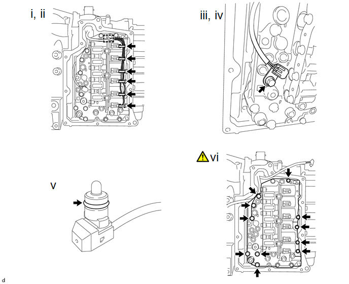
(1) Disengage the clamp to disconnect the transmission wire from the solenoid lock plate.
(2) Disconnect the 6 solenoid valve connectors.
(3) Remove the bolt and temperature sensor clamp from the transmission valve body assembly.
(4) Disconnect the temperature sensor from the transmission valve body assembly.
(5) Remove the O-ring from the temperature sensor.
(6) Remove the 11 bolts and transmission valve body assembly from the transaxle case sub-assembly.
Make sure the manual valve does not fall out when removing the transmission valve body assembly, as the manual valve is not secured to the transmission valve body assembly.
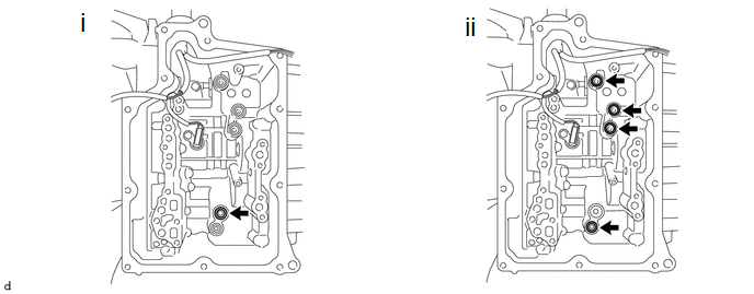
(1) Remove the front oil pump cover gasket from the transaxle case sub-assembly.
(2) Remove the 4 transaxle case gaskets from the transaxle case sub-assembly.


