Toyota Corolla Cross: Installation
INSTALLATION
CAUTION / NOTICE / HINT
COMPONENTS (INSTALLATION)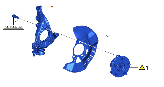
|
Procedure |
Part Name Code |
.png) |
.png) |
.png) |
|
|---|---|---|---|---|---|
|
1 |
FRONT AXLE HUB SUB-ASSEMBLY |
43502C |
|
- |
- |
|
*1 |
STEERING KNUCKLE |
*2 |
FRONT DISC BRAKE DUST COVER |
 |
Tightening torque for "Major areas involving basic vehicle performance such as moving/turning/stopping": N*m (kgf*cm, ft.*lbf) |
- |
- |

|
Procedure |
Part Name Code |
|
|
|
|
|---|---|---|---|---|---|
|
2 |
FRONT AXLE ASSEMBLY |
- |
|
- |
- |
|
3 |
FRONT DRIVE SHAFT ASSEMBLY |
43420 |
|
- |
- |
|
4 |
FRONT LOWER NO. 1 SUSPENSION ARM SUB-ASSEMBLY |
48069 |
- |
- |
- |
|
5 |
TIE ROD END SUB-ASSEMBLY |
45047 |
|
- |
- |
|
6 |
INSTALL FRONT DISC |
43512 |
|
- |
- |
|
7 |
INSTALL FRONT DISC BRAKE CALIPER ASSEMBLY |
- |
|
- |
- |
|
8 |
INSTALL FRONT AXLE SHAFT NUT |
43502H |
|
- |
- |
|
9 |
SEPARATE FRONT DISC BRAKE CALIPER ASSEMBLY |
- |
|
- |
- |
|
10 |
REMOVE FRONT DISC |
43512 |
|
- |
- |
|
11 |
INSPECT FRONT AXLE HUB BEARING LOOSENESS |
- |
|
- |
- |
|
12 |
INSPECT FRONT AXLE HUB RUNOUT |
- |
|
- |
- |
|
13 |
INSTALL FRONT DISC |
43512 |
|
- |
- |
|
14 |
INSTALL FRONT DISC BRAKE CALIPER ASSEMBLY |
- |
|
- |
- |
|
15 |
FRONT SPEED SENSOR |
89543 |
|
- |
- |
|
16 |
STAKE FRONT AXLE SHAFT NUT |
43502H |
|
- |
- |
|
17 |
FRONT WHEEL |
- |
- |
- |
- |
|
18 |
INSPECT AND ADJUST FRONT WHEEL ALIGNMENT |
- |
- |
- |
|
|
19 |
CHECK FOR SPEED SENSOR SIGNAL |
- |
- |
- |
|
|
20 |
PERFORM INITIALIZATION |
- |
- |
- |
|
|
*1 |
FRONT FLEXIBLE HOSE |
- |
- |
|
|
Tightening torque for "Major areas involving basic vehicle performance such as moving/turning/stopping": N*m (kgf*cm, ft.*lbf) |
● |
Non-reusable part |
 |
Toyota Body Grease W |
 |
Do not apply lubricants to the threaded parts |
CAUTION / NOTICE / HINT
HINT:
- Use the same procedure for the RH side and LH side.
- The following procedure is for the LH side.
PROCEDURE
1. INSTALL FRONT AXLE HUB SUB-ASSEMBLY
(1) Secure the steering knuckle between aluminum plates in a vise.
NOTICE:
Do not overtighten the vise.
(2) Install the front axle hub sub-assembly and front disc brake dust cover to the steering knuckle with the 3 bolts.
Torque:
130 N·m {1326 kgf·cm, 96 ft·lbf}
NOTICE:
- Be careful not to damage the speed sensor rotor or contact surfaces.
- Do not allow foreign matter to contact the speed sensor rotor or contact surfaces.
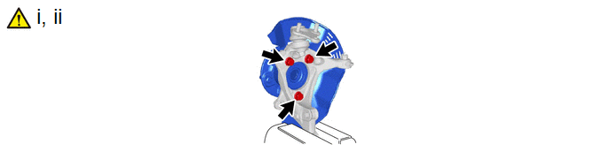
2. INSTALL FRONT AXLE ASSEMBLY
|
|
Toyota Body Grease W |
- |
- |
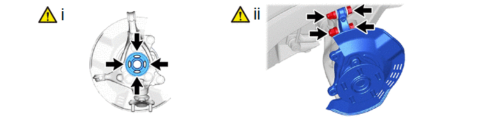
(1) Apply 0.1 to 0.3 g (0.00353 to 0.0105 oz) of Toyota Body Grease W to each of the 4 areas shown in the illustration.
(2) Install the front axle assembly to the front shock absorber assembly with the 2 bolts and 2 nuts.
Torque:
270 N·m {2753 kgf·cm, 199 ft·lbf}
NOTICE:
- Do not apply lubricants to the steering knuckle and shock absorber contact surfaces.
- When installing the nuts, keep the bolts from rotating.
HINT:
The bolts can be installed in either direction, however, make sure that they are both installed in the same direction.
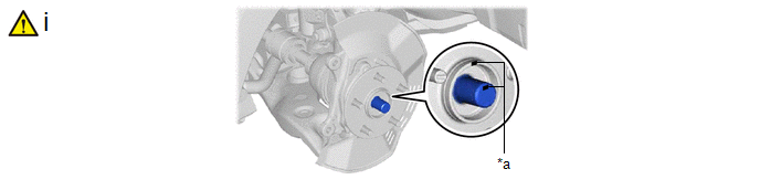
3. INSTALL FRONT DRIVE SHAFT ASSEMBLY
|
*a |
Matchmark |
- |
- |
(1) Align the matchmarks on the front drive shaft assembly and front axle hub sub-assembly, and install the front drive shaft assembly to the front axle assembly.
NOTICE:
- Do not push the front axle assembly towards the outside of the vehicle any further than necessary.
- Check that there is no foreign matter on the speed sensor rotor or contact surfaces.
- Do not damage the front drive shaft outboard joint boot.
- Do not damage the front disc brake dust cover.
- Do not damage the speed sensor rotor.
4. CONNECT FRONT LOWER NO. 1 SUSPENSION ARM SUB-ASSEMBLY
Torque:
92 N·m {938 kgf·cm, 68 ft·lbf}
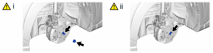
5. CONNECT TIE ROD END SUB-ASSEMBLY
|
|
Click here |
6. INSTALL FRONT DISC
|
|
Click here |
7. INSTALL FRONT DISC BRAKE CALIPER ASSEMBLY
|
|
Click here |
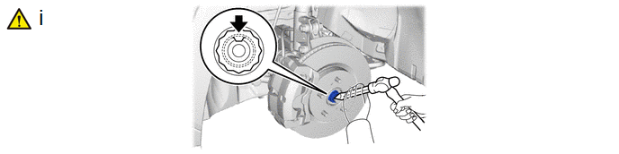
8. INSTALL FRONT AXLE SHAFT NUT
(1) Clean the threaded parts on the front drive shaft assembly and a new front axle shaft nut using non-residue solvent.
NOTICE:
- Be sure to perform this work even when using a new front drive shaft assembly.
- Keep the threaded parts free of oil and foreign matter.
(2) Using a 30 mm deep socket wrench, while applying the brakes, temporarily install the front axle shaft nut.
Torque:
216 N·m {2203 kgf·cm, 159 ft·lbf}
NOTICE:
Stake the front axle shaft nut after inspecting for looseness and runout in the following steps.
9. SEPARATE FRONT DISC BRAKE CALIPER ASSEMBLY
|
|
Click here |
10. REMOVE FRONT DISC
|
|
Click here |
11. INSPECT FRONT AXLE HUB BEARING LOOSENESS
Click here .gif)
12. INSPECT FRONT AXLE HUB RUNOUT
Click here
13. INSTALL FRONT DISC
|
|
Click here |
14. INSTALL FRONT DISC BRAKE CALIPER ASSEMBLY
|
|
Click here |
15. INSTALL FRONT SPEED SENSOR
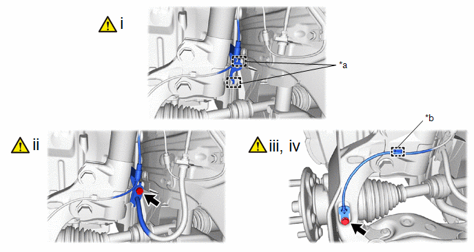
|
*a |
Hook |
*b |
Clamp |
(1) Set the 2 hooks of the front speed sensor to the front shock absorber assembly.
NOTICE:
Do not twist the front speed sensor when installing it.
(2) Install the front speed sensor and front flexible hose to the front shock absorber assembly with the bolt.
Torque:
29 N·m {296 kgf·cm, 21 ft·lbf}
NOTICE:
Do not twist the front flexible hose when installing it.
(3) Install the front speed sensor to the steering knuckle with the bolt.
Torque:
8.5 N·m {87 kgf·cm, 75 in·lbf}
NOTICE:
- Prevent foreign matter from attaching to the front speed sensor tip.
- Firmly insert the front speed sensor body into the steering knuckle before tightening the bolt.
- After installing the front speed sensor to the steering knuckle, make sure that there is no clearance between the front speed sensor stay and steering knuckle. Also make sure that no foreign matter is stuck between the parts.
- Do not twist the front speed sensor when installing it.
(4) Engage the clamp to the front shock absorber assembly.
NOTICE:
Do not twist the front speed sensor when installing it.
16. STAKE FRONT AXLE SHAFT NUT
(1) Using a chisel and hammer, stake the front axle shaft nut.
17. INSTALL FRONT WHEEL
Click here
18. INSPECT AND ADJUST FRONT WHEEL ALIGNMENT
Click here
19. CHECK FOR SPEED SENSOR SIGNAL
- for HEV Model:
Click here
- for Gasoline Model:
Click here
20. PERFORM INITIALIZATION
|
Parking assist monitor system |
|
|
Automatic headlight beam level control system |
|


