Toyota Corolla Cross: Torque Converter Clutch Pressure Control Solenoid Control Circuit Performance/Stuck Off (P275600,P27567E)
DESCRIPTION
Using the current from the TCM, the shift solenoid valve SLU controls the lock-up clutch pressure, and performs lock-up and flex lock-up control.
The TCM compares the engagement condition of the lock-up clutch with the lock-up schedule in the TCM memory to detect mechanical malfunctions of the shift solenoid valve SLU, transmission valve body assembly and torque converter assembly.
|
DTC No. |
Detection Item |
DTC Detection Condition |
Trouble Area |
MIL |
Memory |
Note |
|---|---|---|---|---|---|---|
|
P275600 |
Torque Converter Clutch Pressure Control Solenoid Control Circuit Performance/Stuck Off |
When the TCM commands lock-up ON, the difference between the engine speed (NE) and transmission revolution sensor (NT) signal is 250 rpm or more for 1 second or more (2-trip detection logic). |
|
Comes on |
DTC stored |
SAE Code: P2757 |
|
P27567E |
Torque Converter Clutch Pressure Control Solenoid Control Actuator Stuck On |
When the TCM commands lock-up OFF, the difference between the engine speed (NE) and transmission revolution sensor (NT) signal is less than 25 rpm for 1 second or more (1-trip detection logic). |
|
Comes on |
DTC stored |
SAE Code: P2757 |
MONITOR DESCRIPTION
When performing lock-up control (ON/OFF) of the torque converter assembly, the TCM compares the transmission revolution sensor (NT) signal and engine speed (NE) signal to detect mechanical malfunctions in the shift solenoid valves SLU.
If the torque converter does not lock-up while a lock-up ON command is being sent, the TCM detects it as a mechanical malfunction of the shift solenoid valve SLU.
If the difference between the engine speed (NE) signal and transmission revolution sensor (NT) signal is outside of the threshold, the TCM detects the malfunction, illuminates the MIL and stores a DTC.
MONITOR STRATEGY
|
Related DTCs |
P2757: Torque converter clutch pressure control solenoid (Shift solenoid valve SLU)/Functional check |
|
Required sensors/Components |
Crankshaft position sensor Transmission revolution sensor (NT) CVT fluid temperature sensor Engine coolant temperature sensor Oil pressure sensor Shift solenoid valve SL1 Shift solenoid valve SL2 Shift solenoid valve SLP Shift solenoid valve SLS Shift solenoid valve SLU |
|
Frequency of operation |
Continuous |
|
Duration |
OFF malfunction (A): 2 sec. OFF malfunction (B): 2 sec. ON malfunction: 1 sec. |
|
MIL operation |
OFF malfunction (A) and (B): 2 driving cycles ON malfunction: 1 driving cycle |
|
Sequence of operation |
None |
TYPICAL ENABLING CONDITIONS
All|
ETC system (Electronic throttle control system) |
Not system down (MIL illuminated by following codes: P0121, P0122, P0123, P0222, P0223, P0604, P0606, P0607, P060D, P060E, P0657, P0658, P1607, P16B0, P2102, P2103, P2111, P2112, P2119, P2135) |
|
KCS sensor circuit (Knock sensor) |
Not circuit malfunction (MIL illuminated by following codes: P0327, P0328) |
|
ECT sensor circuit (Engine coolant temperature sensor) |
Not circuit malfunction (MIL illuminated by following codes: P0117, P0118) |
|
IAT sensor circuit (Intake air temperature sensor) |
Not circuit malfunction (MIL illuminated by following codes: P0112, P0113) |
|
Crankshaft position sensor "A" circuit (Crankshaft position sensor) |
Not circuit malfunction (MIL illuminated by following codes: P0335, P0337, P0338) |
|
CAN communication between ECM and TCM |
Not system down (MIL illuminated by following codes: U0100, U0101) |
|
Low voltage flag |
OFF |
|
Pressure control solenoid "J" circuit (Shift solenoid valve SLP) |
Not circuit malfunction (MIL illuminated by following codes: P2826, P2827) |
|
Pressure control solenoid "K" circuit (Shift solenoid valve SLS) |
Not circuit malfunction (MIL illuminated by following codes: P282F, P2830) |
|
Torque converter clutch pressure control solenoid circuit (Shift solenoid valve SLU) |
Not circuit malfunction (MIL illuminated by following codes: P2763, P2764) |
|
Pressure control solenoid "A" circuit (Shift solenoid valve SL1) |
Not circuit malfunction (MIL illuminated by following codes: P0962, P0963) |
|
Pressure control solenoid "B" circuit (Shift solenoid valve SL2) |
Not circuit malfunction (MIL illuminated by following codes: P0966, P0967) |
|
Pressure control solenoid "M" circuit (Shift solenoid valve SLG) |
Not circuit malfunction (MIL illuminated by following codes: P08CA, P08CB) |
|
Transmission fluid temperature sensor "A" circuit (CVT fluid temperature sensor) |
Not circuit malfunction (MIL illuminated by following codes: P0712, P0713) |
|
Turbine speed sensor "A" circuit (Transmission revolution sensor (NT)) |
Not circuit malfunction (MIL illuminated by following codes: P0717, P07BF, P07C0) |
|
Intermediate shaft speed sensor "C" circuit (Transmission revolution sensor (NSS)) |
Not circuit malfunction (MIL illuminated by following codes: P07C9, P07CA, P2751) |
|
Gear shift position circuit |
Not circuit malfunction (MIL illuminated by following codes: P0916, P0917) |
|
Output speed sensor circuit (Transmission revolution sensor (NOUT)) |
Not circuit malfunction (MIL illuminated by following codes: P0722, P077C, P077D) |
|
Intermediate shaft speed sensor "B" circuit (Transmission revolution sensor (NC1)) |
Not circuit malfunction (MIL illuminated by following codes: P07C7, P07C8, P2747) |
|
Ignition switch |
ON |
|
Any of the following conditions are met: (a) or (b) |
- |
|
(a) Gear mode clutch |
Engaged |
|
(b) Belt mode clutch |
Engaged |
|
Engine speed |
1000 rpm or more |
|
Shift solenoid valve SLP |
Operating shift control by TCM command |
|
Engine speed |
550 rpm or more |
|
Transmission fluid temperature |
-10°C (14°F) or more |
|
Time after following condition is met |
0.5 sec. or more |
|
- l Variation of the accelerator pedal angle l (within 32.768 msec.) |
Less than 0.5% |
|
Shift solenoid valve SLS |
Operating clamping pressure control by TCM command |
|
ECT |
60°C (140°F) or more |
|
Spark advance from MAX. retard timing by KCS control |
0°CA or more |
|
Gear and belt mode clutch |
Either engagement or disengagement |
|
Any of the following conditions are met: (a) or (b) |
- |
|
(a) Gear mode clutch |
Engaged |
|
(b) Belt mode clutch |
Engaged |
|
Calculated input torque at Turbine speed 2000 rpm (Conditions vary with turbine speed) |
74 N*m (755 kgf*cm, 55 ft.*lbf) or more |
|
Engine speed |
500 rpm or more |
|
Accelerator pedal release flag |
OFF |
|
Shift solenoid valve SLP |
Operating shift control by TCM command |
TYPICAL MALFUNCTION THRESHOLDS
OFF malfunction- Both of the following conditions are met: OFF malfunction (A) and (B) OFF
malfunction (A)
OFF malfunction (B) (after OFF malfunction (A) is met)l Engine speed - Turbine speed l
250 rpm or more
TCM indicate lock-up clutch
Engagement
Target clamping pressure
1.4 MPa (14.3 kgf/cm2, 203 psi) or more
Actual clamping pressure - Target clamping pressure
Less than 0.5 MPa (5.1 kgf/cm2, 73 psi)
- ON malfunction
l Engine speed - Turbine speed l
Less than 25 rpm
TCM indicate lock-up clutch
Release
CONFIRMATION DRIVING PATTERN
CAUTION:
When performing the confirmation driving pattern, obey all speed limits and traffic laws.
HINT:
- After repairs have been completed, clear the DTCs and then check that the vehicle has returned to normal by performing the following All Readiness check procedure.
- When clearing the permanent DTCs, refer to the Clear Permanent DTC procedure.
Click here
.gif)
- Clear the DTCs (even if no DTCs are stored, perform the clear DTC procedure).
- Turn the ignition switch off and wait for 2 minutes or more.
- Turn the ignition switch to ON and turn the GTS on.
- Start the engine.
- Drive the vehicle and confirm the lock-up on and off conditions according
to Road Test. [*1]
Click here
HINT:
[*1]: Normal judgment procedure.
The normal judgment procedure is used to complete DTC judgment and also used when clearing permanent DTCs.
- Stop the vehicle.
- Enter the following menus: Powertrain / Transmission / Utility / All Readiness.
- Input the DTC: P275600 or P27567E.
- Check the DTC judgment result.
GTS Display
Description
NORMAL
- DTC judgment completed
- System normal
ABNORMAL
- DTC judgment completed
- System abnormal
INCOMPLETE
- DTC judgment not completed
- Perform driving pattern after confirming DTC enabling conditions
N/A
- Unable to perform DTC judgment
- Number of DTCs which do not fulfill DTC preconditions has reached ECU memory limit
HINT:
- If the judgment result shows NORMAL, the system is normal.
- If the judgment result shows ABNORMAL, the system has a malfunction.
- If the judgment result shows INCOMPLETE or N/A, perform the normal judgment procedure again.
CAUTION / NOTICE / HINT
NOTICE:
- Perform the universal trip to clear permanent DTCs.
Click here
- Perform registration and/or initialization when parts related to the continuously
variable transaxle system are replaced.
Click here
- Check that no DTCs are stored after performing initialization.
Click here
HINT:
If any DTCs other than P275600 or P27567E are output, perform troubleshooting for those DTCs first.
PROCEDURE
|
1. |
CHECK DTC OUTPUT (IN ADDITION TO DTC P275600 AND P27567E) |
(a) Enter the following menus:
Powertrain > Transmission > Trouble Codes(b) Read the DTCs using the GTS.
HINT:
- If DTC P275612 or P275614 is output, perform troubleshooting for that DTC first.
- If DTCs P275612 and P275614 are not output but DTC P281F00 is output, perform troubleshooting for DTC P281F00 first.
|
Result |
Proceed to |
|---|---|
|
Only DTC P275600 and/or P27567E is output |
A |
|
DTC P275600 and/or P27567E and P275612 are output |
B |
|
DTC P275600 and/or P27567E and P275614 are output |
C |
|
DTC P275600 and P281F00 are output |
D |
|
DTC P275600 and/or P27567E and DTCs other than P275612, P275614 and P281F00 are output |
E |
| B | .gif) |
GO TO DTC CHART (DTC P275612) |
| C | |
GO TO DTC CHART (DTC P275614) |
| D | |
GO TO DTC CHART (DTC P281F00) |
| E | |
GO TO DTC CHART |
|
.gif)
|
2. |
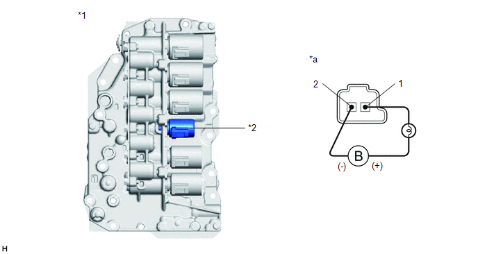
INSPECT TRANSMISSION VALVE BODY ASSEMBLY (SHIFT SOLENOID VALVE SLU) |
(a) Disconnect the transmission wire connector from the shift solenoid valve SLU.
Click here
|
*1 |
Transmission Valve Body Assembly |
*2 |
Shift Solenoid Valve SLU |
|
*a |
Component without harness connected (Shift Solenoid Valve SLU) |
- |
- |
(b) Connect a positive (+) lead from the auxiliary battery with a 21 W bulb to terminal 1 and a negative (-) lead to terminal 2 of the shift solenoid valve SLU connector. Check that the valve moves and makes an operating sound.
OK:
Valve moves and makes an operating sound.
| NG | |
GO TO STEP 5 |
|
|
3. |
REPLACE CONTINUOUSLY VARIABLE TRANSAXLE ASSEMBLY |
Click here
|
|
4. |
REPLACE TORQUE CONVERTER ASSEMBLY |
Click here
| NEXT | |
PERFORM REGISTRATION AND INITIALIZATION for Registration: Click here for Initialization: Click here |
|
5. |
REPLACE TRANSMISSION VALVE BODY ASSEMBLY |
Click here
| NEXT | |
PERFORM REGISTRATION AND INITIALIZATION for Registration: Click here for Initialization: Click here |
READ NEXT:
 Torque Converter Clutch Pressure Control Solenoid Control Circuit Short to Battery
(P275612)
Torque Converter Clutch Pressure Control Solenoid Control Circuit Short to Battery
(P275612)
DESCRIPTION
Using the current from the TCM, the shift solenoid valve SLU controls the lock-up
clutch pressure, and performs lock-up and flex lock-up control.
DTC No.
Detectio
Torque Converter Clutch Pressure Control Solenoid Control Circuit Short to Ground
or Open (P275614)
DESCRIPTION
Refer to DTC P275612.
Click here
DTC No.
Detection Item
DTC Detection Condition
Trouble Area
MIL
Memory
No
Pressure Control Solenoid "J" Performance/Stuck Off (2 Trip Detected) (P281F00,P281F71)
DESCRIPTION
Using the current from the TCM, the shift solenoid valve SLP controls the primary
pulley pressure in accordance with the requested gear ratio to perform gear ratio
changes.
SEE MORE:
 Fail-safe Chart
FAIL-SAFE CHART FAIL-SAFE FUNCTION (a) The following chart shows the status of the front passenger SRS items and passenger airbag ON/OFF indicator operation under failure condition.
Passenger Airbag ON/OFF Indicator
Front Passenger SRS Item
ON Indicator OFF Indicator
Instr
Disassembly
DISASSEMBLY CAUTION / NOTICE / HINT COMPONENTS (DISASSEMBLY)
Procedure Part Name Code
1 PRECAUTION
-
- -
2 DISCONNECT CABLE FROM NEGATIVE AUXILIARY BATTERY TERMINAL
- -
- -
3 REAR DOOR INSIDE HANDLE BEZEL PLUG
