Toyota Corolla Cross: Pressure Control Solenoid "J" Performance/Stuck Off (2 Trip Detected) (P281F00,P281F71)
DESCRIPTION
Using the current from the TCM, the shift solenoid valve SLP controls the primary pulley pressure in accordance with the requested gear ratio to perform gear ratio changes.
|
DTC No. |
Detection Item |
DTC Detection Condition |
Trouble Area |
MIL |
Memory |
Note |
|---|---|---|---|---|---|---|
|
P281F00 |
Pressure Control Solenoid "J" Performance/Stuck Off (2 Trip Detected) |
Any of the following conditions are met (2-trip detection logic):
|
Continuously variable transaxle assembly (Shift solenoid valve SLP) |
Comes on |
DTC stored |
SAE Code: P2820 |
|
P281F71 |
Pressure Control Solenoid "J" Performance/Stuck Off Actuator Stuck |
Any of the following conditions are met (1-trip detection logic):
|
Continuously variable transaxle assembly (Shift solenoid valve SLP) |
Comes on |
DTC stored |
SAE Code: P2820 |
MONITOR DESCRIPTION
P281F00 (Shift solenoid valve SLP OFF stuck): Detection condition from lock-up clutch operation:- Under normal conditions, if the TCM commands lock-up ON, line pressure is
applied to the lock up control valve from the shift solenoid valve SLU. The
lock up control valve then opens to the lock-up ON side of the lock-up clutch
and the lock-up clutch engages.
When the shift solenoid valve SLP is stuck OFF, if the TCM commands lock-up ON, line pressure is applied to the sequence valve from the shift solenoid valve SLP and in turn line pressure from the shift solenoid valve SLG is applied to the lock up control valve.
As a result, the lock up control valve blocks the line pressure from being applied to the lock-up ON side of the lock-up clutch and the lock-up clutch cannot be engaged.
In this case, when the TCM commands lock-up ON, it detects that lock-up is not operating (the difference between the engine speed (NE) signal and transmission revolution sensor (NT) signal exceeds the threshold) and determines that the shift solenoid valve SLP is stuck OFF, illuminates the MIL and stores a DTC.
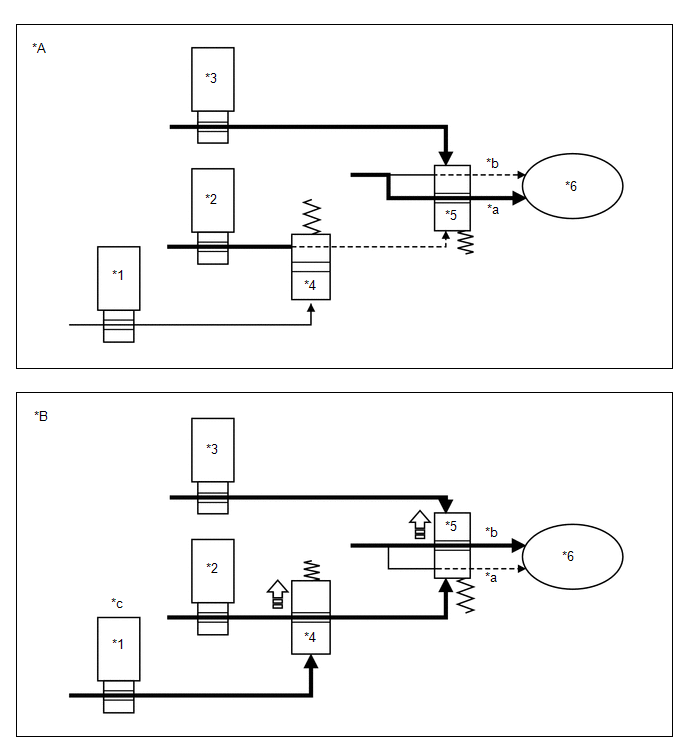
*A
TCM commands lock-up ON when shift solenoid valve SLP normal
*B
TCM commands lock-up ON when shift solenoid valve SLP stuck OFF
*1
Shift Solenoid Valve SLP
*2
Shift Solenoid Valve SLG
*3
Shift Solenoid Valve SLU
*4
Sequence Valve
*5
Lock Up Control Valve
*6
Lock-Up Clutch
*a
Lock-up ON
*b
Lock-up OFF
*c
Shift solenoid valve SLP stuck OFF
-
-
.png)
Oil Pressure Flow
.png)
Valve Movement
- Under normal conditions, when the TCM requests the shift mode be changed
to gear mode, line pressure is applied from the shift solenoid SL1 to engage
the C1 clutch and gear mode is entered.
When the shift solenoid valve SLP is stuck OFF, if the TCM requests the shift mode to be changed to gear mode, line pressure from the shift solenoid valve SLP is applied to the sequence valve and in turn line pressure is applied to the clutch apply control valve.
As a result, the clutch apply control valve blocks the line pressure from being applied to the C1 clutch. The C1 clutch cannot be engaged and the shift mode cannot be changed.
In this case, when the TCM requests the shift mode to be changed to gear mode, it detects that gear mode is not entered (the C1 clutch is not engaged and the difference between the transmission revolution sensor (NT) signal and transmission revolution sensor (NC1) signal exceeds the threshold) and determines that the shift solenoid valve SLP is stuck OFF, illuminates the MIL and stores a DTC.
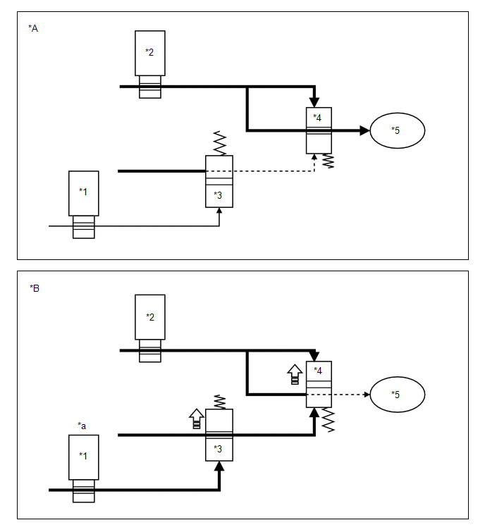
*A
TCM commands C1 clutch engagement when shift solenoid valve SLP normal
*B
TCM commands C1 clutch engagement when shift solenoid valve SLP stuck OFF
*1
Shift Solenoid Valve SLP
*2
Shift Solenoid Valve SL1
*3
Sequence Valve
*4
Clutch Apply Control Valve
*5
C1 Clutch
-
-
*a
Shift solenoid valve SLP stuck OFF
-
-
Oil Pressure Flow
Valve Movement
The TCM compares the actual gear ratio with the target gear ratio. When the actual gear ratio and target gear ratio are different, the TCM detects the malfunction, illuminates the MIL and stores this DTC.
MONITOR STRATEGY
|
Related DTCs |
P2820: Pressure control solenoid "J" (Shift solenoid valve SLP)/Functional check |
|
Required sensors/Components |
Crankshaft position sensor Transmission revolution sensor (NT) Transmission revolution sensor (NC1) Transmission revolution sensor (NSS) Transmission revolution sensor (NOUT) Vehicle speed sensor CVT fluid temperature sensor Engine coolant temperature sensor Oil pressure sensor Shift solenoid valve SL1 Shift solenoid valve SL2 Shift solenoid valve SLP Shift solenoid valve SLS Shift solenoid valve SLG |
|
Frequency of operation |
Continuous |
|
Duration |
Case 1:
|
|
MIL operation |
Case 1: 1 driving cycle Case 2: 2 driving cycles |
|
Sequence of operation |
None |
TYPICAL ENABLING CONDITIONS
All|
ETC system (Electronic throttle control system) |
Not system down (MIL illuminated by following codes: P0121, P0122, P0123, P0222, P0223, P0604, P0606, P0607, P060D, P060E, P0657, P0658, P1607, P16B0, P2102, P2103, P2111, P2112, P2119, P2135) |
|
KCS sensor circuit (Knock sensor) |
Not circuit malfunction (MIL illuminated by following codes: P0327, P0328) |
|
ECT sensor circuit (Engine coolant temperature sensor) |
Not circuit malfunction (MIL illuminated by following codes: P0117, P0118) |
|
IAT sensor circuit (Intake air temperature sensor) |
Not circuit malfunction (MIL illuminated by following codes: P0112, P0113) |
|
Crankshaft position sensor "A" circuit (Crankshaft position sensor) |
Not circuit malfunction (MIL illuminated by following codes: P0335, P0337, P0338) |
|
CAN communication between ECM and TCM |
Not system down (MIL illuminated by following codes: U0100, U0101) |
|
Low voltage flag |
OFF |
|
Transmission fluid pressure sensor "A" circuit (Oil pressure sensor) |
Not circuit malfunction (MIL illuminated by following codes: P0842, P0843) |
|
Pressure control solenoid "J" circuit (Shift solenoid valve SLP) |
Not circuit malfunction (MIL illuminated by following codes: P2826, P2827) |
|
Pressure control solenoid "K" circuit (Shift solenoid valve SLS) |
Not circuit malfunction (MIL illuminated by following codes: P282F, P2830) |
|
Torque converter clutch pressure control solenoid circuit (Shift solenoid valve SLU) |
Not circuit malfunction (MIL illuminated by following codes: P2763, P2764) |
|
Pressure control solenoid "A" circuit (Shift solenoid valve SL1) |
Not circuit malfunction (MIL illuminated by following codes: P0962, P0963) |
|
Pressure control solenoid "B" circuit (Shift solenoid valve SL2) |
Not circuit malfunction (MIL illuminated by following codes: P0966, P0967) |
|
Pressure Control Solenoid "M" circuit (Shift solenoid valve SLG) |
Not circuit malfunction (MIL illuminated by following codes: P08CA, P08CB) |
|
Transmission fluid temperature sensor "A" circuit (CVT fluid temperature sensor) |
Not circuit malfunction (MIL illuminated by following codes: P0712, P0713) |
|
Turbine speed sensor "A" circuit (Transmission revolution sensor (NT)) |
Not circuit malfunction (MIL illuminated by following codes: P0717, P07BF, P07C0) |
|
Intermediate shaft speed sensor "C" circuit (Transmission revolution sensor (NSS)) |
Not circuit malfunction (MIL illuminated by following codes: P07C9, P07CA, P2751) |
|
Output speed sensor circuit (Transmission revolution sensor (NOUT)) |
Not circuit malfunction (MIL illuminated by following codes: P0722, P077C, P077D) |
|
Intermediate shaft speed sensor "B" circuit (Transmission revolution sensor (NC1)) |
Not circuit malfunction (MIL illuminated by following codes: P07C7, P07C8, P2747) |
|
Gear shift position circuit |
Not circuit malfunction (MIL illuminated by following codes: P0916, P0917) |
- OFF malfunction
ON malfunction (1st judgment)Tire
Not slipping
ECT
60°C (140°F) or more
Spark advance from MAX. retard timing by KCS control
0°CA or more
Shift solenoid valve SLP
Operating shift control by TCM command
Engine speed
500 rpm or more
Primary sheave speed
100 rpm or more
Secondary sheave speed
150 rpm or more
Output speed
150 rpm or more
Transmission fluid temperature
-10°C (14°F) or more and less than 140°C (284°F)
l Target clamping pressure - Actual clamping pressure l
Less than 0.5 MPa (5.1 kgf/cm2, 73 psi)
Actual clamping pressure
0.4 MPa (4.1 kgf/cm2, 58 psi) or more
Any of the following conditions are met: (a) or (b)
-
(a) Gear mode clutch
Engaged
(b) Belt mode clutch
Engaged
ON malfunction (2nd judgment)Tire
Not slipping
ECT
60°C (140°F) or more
Spark advance from MAX. retard timing by KCS control
0°CA or more
Shift solenoid valve SLP
Operating shift control by TCM command
Engine speed
500 rpm or more
Primary sheave speed
100 rpm or more
Secondary sheave speed
150 rpm or more
Output speed
150 rpm or more
Transmission fluid temperature
-10°C (14°F) or more and less than 140°C (284°F)
l Target clamping pressure - Actual clamping pressure l
Less than 0.5 MPa (5.1 kgf/cm2, 73 psi)
Any of the following conditions are met: (a) or (b)
-
(a) Gear mode clutch
Engaged
(b) Belt mode clutch
Engaged
Tire
Not slipping
ECT
60°C (140°F) or more
Spark advance from MAX. retard timing by KCS control
0°CA or more
Shift solenoid valve SLP
Operating shift control by TCM command
Engine speed
500 rpm or more
Primary sheave speed
100 rpm or more
Secondary sheave speed
150 rpm or more
Output speed
150 rpm or more
Transmission fluid temperature
-10°C (14°F) or more and less than 140°C (284°F)
l Target clamping pressure - Actual clamping pressure l
Less than 0.5 MPa (5.1 kgf/cm2, 73 psi)
Any of the following conditions are met: (a) or (b)
-
(a) Gear mode clutch
Engaged
(b) Belt mode clutch
Engaged
Actual clamping pressure
0.4 MPa (4.1 kgf/cm2, 58 psi) or more
Following condition is met once after 1st judgment
-
- Vehicle speed
Less than 10 km/h (6 mph)
- OFF malfunction (A)
OFF malfunction (B)Shift solenoid valve SLP
Operating shift control by TCM command
Engine speed
500 rpm or more
Synchronizer
Engaged
Turbine speed
More than 0 rpm
Any of the following conditions are met: (a) or (b)
-
(a) Gear mode clutch speed
More than 0 rpm
(b) All of the following conditions are met
-
- Gear mode clutch speed
0 rpm
- Output speed
0 rpm
OFF malfunction (C)Engine speed
550 rpm or more
Transmission fluid temperature
-10°C (14°F) or more
Time after following condition is met
0.5 sec. or more
- l Variation of the accelerator pedal angle l
(within 32.768 msec.)
Less than 0.5%
Shift solenoid valve SLS
Operating clamping pressure control by TCM command
ECT
60°C (140°F) or more
Spark advance from MAX. retard timing by KCS control
0°CA or more
Gear and belt mode clutch
Either engagement or disengagement
OFF malfunction (D)Shift solenoid valve SLP
Operating shift control by TCM command
Engine speed
500 rpm or more
Secondary sheave torque
40 N*m (408 kgf*cm, 30 ft.*lbf) or more
Accelerator pedal release flag
OFF
OFF malfunction (E)Any of the following conditions are met: (a) or (b)
-
(a) Gear mode clutch
Engaged
(b) Reverse clutch
Engaged
Engine speed
1000 rpm or more
Shift solenoid valve SLP
Operating shift control by TCM command
Engine speed
550 rpm or more
Transmission fluid temperature
-10°C (14°F) or more
Time after following condition is met
0.5 sec. or more
- l Variation of the accelerator pedal angle l
(within 32.768 msec.)
Less than 0.5%
Shift solenoid valve SLS
Operating clamping pressure control by TCM command
ECT
60°C (140°F) or more
Spark advance from MAX. retard timing by KCS control
0°CA or more
Gear and belt mode clutch
Either engagement or disengagement
TYPICAL MALFUNCTION THRESHOLDS
Case 1:- OFF malfunction
ON malfunctionTarget gear ratio
2 or more
Actual gear ratio
Less than 0.55
It is necessary to have 2 judgments per driving cycle. 2nd judgment: pending fault code ON
Target gear ratio
Less than 1.1
Actual gear ratio
1.8 or more
- Following conditions (A), (B) and (C), or (D) and (E) are met: OFF malfunction
(A)
OFF malfunction (B) (after OFF malfunction (A) is met)TCM indicate gear mode clutch
Engagement
l Turbine Speed - Gear mode clutch speed l
More than 200 rpm
OFF malfunction (C) (after OFF malfunction (A) and (B) are met)Target clamping pressure
1.4 MPa (14.3 kgf/cm2, 203 psi) or more
l Actual clamping pressure - Target clamping pressure l
Less than 0.5 MPa (5.1 kgf/cm2, 73 psi)
OFF malfunction (D)TCM indicate belt mode clutch
Engagement
l Secondary sheave speed - Output speed l
Less than 25 rpm
OFF malfunction (E) (after OFF malfunction (D) is met)TCM indicate lock-up clutch
Engagement
l Engine speed - Turbine speed l
250 rpm or more
Target clamping pressure
1.4 MPa (14.3 kgf/cm2, 203 psi) or more
l Actual clamping pressure - Target clamping pressure l
Less than 0.5 MPa (5.1 kgf/cm2, 73 psi)
CONFIRMATION DRIVING PATTERN
CAUTION:
When performing the confirmation driving pattern, obey all speed limits and traffic laws.
HINT:
- After repairs have been completed, clear the DTCs and then check that the vehicle has returned to normal by performing the following All Readiness check procedure.
- When clearing the permanent DTCs, refer to the Clear Permanent DTC procedure.
Click here
.gif)
- Clear the DTCs (even if no DTCs are stored, perform the clear DTC procedure).
- Turn the ignition switch off and wait for 2 minutes or more.
- Turn the ignition switch to ON and turn the GTS on.
- Start the engine.
- Perform the D Position Shift Test inspection in Road Test. [*1]
Click here
HINT:
[*1]: Normal judgment procedure.
The normal judgment procedure is used to complete DTC judgment and also used when clearing permanent DTCs.
- Stop the vehicle.
- Enter the following menus: Powertrain / Transmission / Utility / All Readiness.
- Input the DTC: P281F00 or P281F71.
- Check the DTC judgment result.
GTS Display
Description
NORMAL
- DTC judgment completed
- System normal
ABNORMAL
- DTC judgment completed
- System abnormal
INCOMPLETE
- DTC judgment not completed
- Perform driving pattern after confirming DTC enabling conditions
N/A
- Unable to perform DTC judgment
- Number of DTCs which do not fulfill DTC preconditions has reached ECU memory limit
HINT:
- If the judgment result shows NORMAL, the system is normal.
- If the judgment result shows ABNORMAL, the system has a malfunction.
- If the judgment result shows INCOMPLETE or N/A, perform the normal judgment procedure again.
CAUTION / NOTICE / HINT
NOTICE:
- Perform the universal trip to clear permanent DTCs.
Click here
- Perform registration and/or initialization when parts related to the continuously
variable transaxle system are replaced.
Click here
- Check that no DTCs are stored after performing initialization.
Click here
HINT:
If any DTCs other than P281F00 or P281F71 are output, perform troubleshooting for those DTCs first.
PROCEDURE
|
1. |
CHECK DTC OUTPUT (IN ADDITION TO DTC P281F00 AND P281F71) |
(a) Enter the following menus:
Powertrain > Transmission > Trouble Codes(b) Read the DTCs using the GTS.
HINT:
If DTC P281F12 or P281F14 is output, perform troubleshooting for that DTC first.
|
Result |
Proceed to |
|---|---|
|
Only DTC P281F00 and/or P281F71 is output |
A |
|
DTC P281F00 and/or P281F71 and P07457F, P07757F or P275600 are output |
B |
|
DTC P281F00 and/or P281F71 and P281F12 are output |
C |
|
DTC P281F00 and/or P281F71 and P281F14 are output |
D |
|
DTC P281F00 and/or P281F71 and DTCs other than P07457F, P07757F, P275600, P281F12 and P281F14 are output |
E |
| B | .gif) |
GO TO STEP 2 |
| C | |
GO TO DTC CHART (DTC P281F12) |
| D | |
GO TO DTC CHART (DTC P281F14) |
| E | |
GO TO DTC CHART |
|
.gif)
|
2. |
REPLACE CONTINUOUSLY VARIABLE TRANSAXLE ASSEMBLY |
Click here
| NEXT | |
PERFORM REGISTRATION AND INITIALIZATION for Registration: Click here for Initialization: Click here |
READ NEXT:
 Pressure Control Solenoid "J" Circuit Short to Battery (P281F12)
DESCRIPTION
Using the current from the TCM, the shift solenoid valve SLP controls the primary
pulley pressure in accordance with the requested gear ratio to perform gear ratio
changes.
Pressure Control Solenoid "J" Circuit Short to Ground or Open (P281F14)
DESCRIPTION
Refer to DTC P281F12.
Click here
DTC No.
Detection Item
DTC Detection Condition
Trouble Area
MIL
Memory
No
Pressure Control Solenoid "K" Circuit Short to Battery (P282812)
DESCRIPTION
Using the current from the TCM, the shift solenoid valve SLS controls the secondary
pulley pressure and belt clamping pressure in accordance with the input shaft torque.
DTC
SEE MORE:
 Hybrid/EV Battery "A" Voltage Sensor/Boosting Converter Voltage Sensor "A" Signal Compare Failure (P1C2D62)
DTC SUMMARY MALFUNCTION DESCRIPTION The hybrid vehicle control ECU detects a VB sensor or VL sensor malfunction.
The cause of this malfunction may be one of the following: Inverter voltage (VB or VL) sensor internal circuit malfunction
Voltage sensor malfunction
Motor generator contro
Right Frontal Restraints Sensor Signal Below Allowable Range (B009584)
DESCRIPTION
DTC No. Detection Item
DTC Detection Condition Trouble Area
Warning Indicate Test Mode / Check Mode
B009584 Right Frontal Restraints Sensor Signal Below Allowable Range
One of the following conditions is met:
Front airbag sensor RH malfuncti
