Toyota Corolla Cross: Throttle/Pedal Position Sensor/Switch "D" Circuit Short to Battery (P212012)
DESCRIPTION
HINT:
These DTCs relate to the accelerator pedal position sensor.
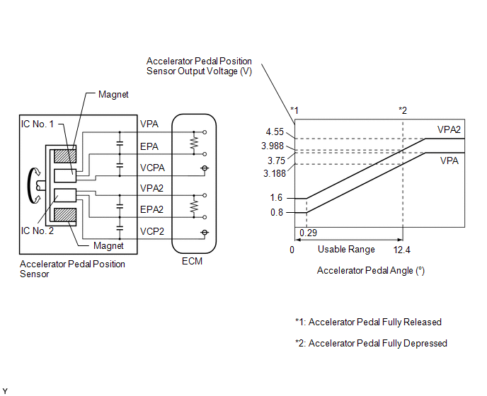
The accelerator pedal position sensor is built into the accelerator pedal sensor assembly and has 2 sensor circuits: VPA (main) and VPA2 (sub). This sensor is a non-contact type sensor and uses Hall-effect elements in order to yield accurate signals even in extreme driving conditions, such as at high speeds as well as very low speeds. The voltage, which is applied to terminals VPA and VPA2 of the ECM, varies between 0.5 V and 4.75 V in proportion to the operating angle of the accelerator pedal (throttle valve). A signal from VPA indicates the actual accelerator pedal opening angle (throttle valve opening angle) and is used for engine control. A signal from VPA2 conveys the status of the VPA circuit and is used to check the accelerator pedal position sensor itself.
The ECM monitors the actual accelerator pedal opening angle (throttle valve opening angle) through the signals from VPA and VPA2, and controls the throttle actuator according to these signals.
|
DTC No. | Detection Item |
DTC Detection Condition | Trouble Area |
MIL | Note |
|---|---|---|---|---|---|
|
P212012 | Throttle/Pedal Position Sensor/Switch "D" Circuit Short to Battery |
Diagnosis condition:
Abnormal condition:
Malfunction time:
Trip logic:
Detection conditions:
Sensors/components used for detection:
|
| Comes on |
|
HINT:
When any of these DTCs are output, check the accelerator pedal position sensor voltage using the GTS. Enter the following menus: Powertrain / Engine / Data List / Accelerator Position Sensor No.1 Voltage and Accelerator Position Sensor No.2 Voltage.
|
Trouble Area |
Accelerator Pedal Fully Released |
Accelerator Pedal Fully Depressed | ||
|---|---|---|---|---|
|
Accelerator Position Sensor No.1 Voltage |
Accelerator Position Sensor No.2 Voltage |
Accelerator Position Sensor No.1 Voltage |
Accelerator Position Sensor No.2 Voltage | |
|
Open in VC circuit | 0 to 0.2 V |
0 to 0.2 V | 0 to 0.2 V |
0 to 0.2 V |
|
Open or ground short in VPA circuit |
0 to 0.2 V | 1.2 to 2.0 V |
0 to 0.2 V | 3.4 to 4.75 V |
|
Open or ground short in VPA2 circuit |
0.5 to 1.1 V | 0 to 0.2 V |
2.6 to 4.5 V | 0 to 0.2 V |
|
Open in EPA circuit | 4.5 to 4.98 V |
4.5 to 4.98 V | 4.5 to 4.98 V |
4.5 to 4.98 V |
|
Normal condition | 0.5 to 1.1 V |
1.2 to 2.0 V | 2.6 to 4.5 V |
3.4 to 4.75 V |
HINT:
Accelerator pedal positions are expressed as voltages.
MONITOR DESCRIPTION
When the ignition switch is turned ON and the VPA voltage is 4.8 V or higher for 2 seconds or more, the ECM determines that the accelerator pedal sensor assembly circuit is malfunctioning and illuminates the MIL and stores a DTC.
MONITOR STRATEGY
|
Related DTCs | P2123: Accelerator pedal position sensor 1 range check (high voltage) |
|
Required Sensors/Components (Main) | Accelerator pedal sensor assembly |
|
Required Sensors/Components (Related) |
- |
| Frequency of Operation |
Continuous |
| Duration |
2.0 seconds |
| MIL Operation |
Immediate |
| Sequence of Operation |
None |
TYPICAL ENABLING CONDITIONS
|
Monitor runs whenever the following DTCs are not stored |
None |
TYPICAL MALFUNCTION THRESHOLDS
|
VPA voltage | 4.8 V or higher |
CONFIRMATION DRIVING PATTERN
HINT:
- After repair has been completed, clear the DTC and then check that the vehicle has returned to normal by performing the following All Readiness check procedure.
Click here
.gif)
- When clearing the permanent DTCs, refer to the "CLEAR PERMANENT DTC" procedure.
Click here
- Connect the GTS to the DLC3.
- Turn the ignition switch to ON.
- Turn the GTS on.
- Clear the DTCs (even if no DTCs are stored, perform the clear DTC procedure).
- Turn the ignition switch off and wait for at least 30 seconds.
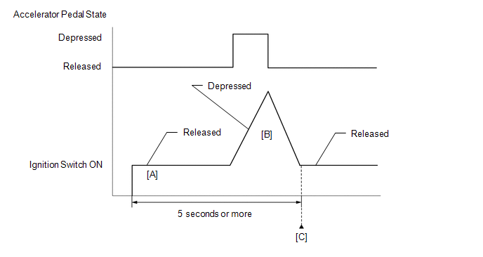
- Turn the ignition switch to ON [A].
- Turn the GTS on.
- Fully depress and release the accelerator pedal [B].
- Check that 5 seconds or more have elapsed since the ignition switch to ON.
- Enter the following menus: Powertrain / Engine / Trouble Codes [C].
- Read the pending DTCs.
HINT:
- If a pending DTC is output, the system is malfunctioning.
- If a pending DTC is not output, perform the following procedure.
- Enter the following menus: Powertrain / Engine / Utility / All Readiness.
- Proceed to the next screen and enter the DTC to be checked.
- Check the DTC judgment result.
GTS Display
Description
NORMAL
- DTC judgment completed
- System normal
ABNORMAL
- DTC judgment completed
- System abnormal
INCOMPLETE
- DTC judgment not completed
- Perform driving pattern after confirming DTC enabling conditions
HINT:
- If the judgment result is NORMAL, the system is normal.
- If the judgment result is ABNORMAL, the system is malfunctioning.
- If the judgment result is INCOMPLETE, perform steps [B] through [C] again.
- [A] to [C]: Normal judgment procedure.
The normal judgment procedure is used to complete DTC judgment and also used when clearing permanent DTCs.
- When clearing the permanent DTCs, do not disconnect the cable from the auxiliary battery terminal or attempt to clear the DTCs during this procedure, as doing so will clear the universal trip and normal judgment histories.
FAIL-SAFE
When these DTCs are stored, the ECM enters fail-safe mode. If either of the 2 sensor circuits malfunctions, the ECM limits the engine output. If both of the circuits malfunction, the ECM regards the accelerator pedal as being released. As a result, the throttle valve is closed and the engine idles.
Fail-safe mode continues until a pass condition is detected, and the ignition switch is turned off.
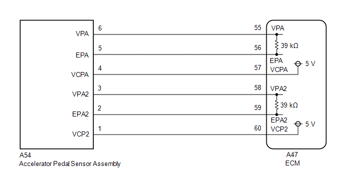
WIRING DIAGRAM
CAUTION / NOTICE / HINT
HINT:
Read Freeze Frame Data using the GTS. The ECM records vehicle and driving condition information as Freeze Frame Data the moment a DTC is stored. When troubleshooting, Freeze Frame Data can help determine if the vehicle was moving or stationary, if the engine was warmed up or not, if the air fuel ratio was lean or rich, and other data from the time the malfunction occurred.
PROCEDURE
| 1. |
CHECK TERMINAL VOLTAGE (ACCELERATOR PEDAL SENSOR ASSEMBLY) |
|
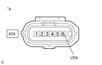
*a | Front view of wire harness connector (to Accelerator Pedal Sensor Assembly) |
HINT:
Make sure that the connector is properly connected. If it is not, securely connect it and check for DTCs again.
(a) Disconnect the accelerator pedal sensor assembly connector.
(b) Turn the ignition switch to ON.
(c) Measure the voltage according to the value(s) in the table below.
Standard Voltage:
|
Tester Connection | Condition |
Specified Condition |
|---|---|---|
|
A54-6 (VPA) - Body ground |
Ignition switch ON | Below 1 V |
HINT:
If the value differs from standard, there may be a short in the power source circuit.
| NG | .gif) | GO TO STEP 4 |
|
.gif)
| 2. |
CHECK HARNESS AND CONNECTOR (ACCELERATOR PEDAL SENSOR ASSEMBLY - BODY GROUND) |
(a) Disconnect the accelerator pedal sensor assembly connector.
(b) Measure the resistance according to the value(s) in the table below.
Standard Resistance:
|
Tester Connection | Condition |
Specified Condition |
|---|---|---|
|
A54-5 (EPA) - Body ground |
Always | Below 1 Ω |
| OK | | REPLACE ACCELERATOR PEDAL SENSOR ASSEMBLY |
|
| 3. |
CHECK HARNESS AND CONNECTOR (ACCELERATOR PEDAL SENSOR ASSEMBLY - ECM) |
(a) Disconnect the accelerator pedal sensor assembly connector.
(b) Disconnect the ECM connector.
(c) Measure the resistance according to the value(s) in the table below.
Standard Resistance:
|
Tester Connection | Condition |
Specified Condition |
|---|---|---|
|
A54-5 (EPA) - A47-56 (EPA) |
Always | Below 1 Ω |
| OK | | REPLACE ECM
|
| NG | | REPAIR OR REPLACE HARNESS OR CONNECTOR |
| 4. |
CHECK HARNESS AND CONNECTOR (ACCELERATOR PEDAL SENSOR ASSEMBLY - ECM) |
(a) Disconnect the accelerator pedal sensor assembly connector.
(b) Disconnect the ECM connector.
(c) Measure the resistance according to the value(s) in the table below.
Standard Resistance:
|
Tester Connection | Condition |
Specified Condition |
|---|---|---|
|
A54-6 (VPA) or A47-55 (VPA) - Body ground and other terminals |
Always | 10 kΩ or higher |
| OK | | REPLACE ECM
|
| NG | | REPAIR OR REPLACE HARNESS OR CONNECTOR |


