Toyota Corolla Cross: Throttle/Pedal Position Sensor/Switch "D" Circuit Voltage Out of Range (P21201C,P212099)
DESCRIPTION
HINT:
These DTCs relate to the accelerator pedal position sensor.
Refer to DTC P212012.
Click here .gif)
|
DTC No. | Detection Item |
DTC Detection Condition | Trouble Area |
MIL | Note |
|---|---|---|---|---|---|
|
P21201C | Throttle/Pedal Position Sensor/Switch "D" Circuit Voltage Out of Range |
Diagnosis condition:
Abnormal condition:
Malfunction time:
Trip logic:
Detection conditions:
Sensors/components used for detection:
|
| Comes on |
|
| P212099 |
Throttle/Pedal Position Sensor/Switch "D" Exceeded Learning Limit |
Diagnosis condition:
Abnormal condition:
Malfunction time:
Trip logic:
Detection conditions:
Sensors/components used for detection:
|
| Comes on |
|
MONITOR DESCRIPTION
P21201CWhen the ignition switch is turned ON and the difference between VPA and VPA2 is greater than or equal to the specified value for 0.5 seconds or more, the ECM determines that the accelerator pedal sensor assembly circuit is malfunctioning and illuminates the MIL and stores a DTC.
P212099When the ignition switch is turned ON, the accelerator pedal is fully released and the difference in the calculated voltage of VPA and VPA2 is less than 0.4 V or more than 1.2 V, the ECM determines that the accelerator pedal sensor assembly circuit is malfunctioning and illuminates the MIL and stores a DTC.
MONITOR STRATEGY
|
Related DTCs | P2121: Accelerator pedal position sensor rationality |
|
Required Sensors/Components (Main) | Accelerator pedal sensor assembly |
|
Required Sensors/Components (Related) |
- |
| Frequency of Operation |
Continuous |
| Duration |
2 seconds: P2121 (case 1) 0.5 seconds: P2121 (case 2) |
|
MIL Operation | Immediate |
|
Sequence of Operation | None |
TYPICAL ENABLING CONDITIONS
|
Accelerator pedal position sensor circuit fail (P2120, P2122, P2123, P2125, P2127, P2128, P2138) (Pending / MIL) |
Not detected |
TYPICAL MALFUNCTION THRESHOLDS
P2121: (Case 1)|
Difference between VPA voltage and VPA2 voltage (learned value of accelerator off position) |
Less than 0.4 V, or higher than 1.2 V |
|
All of the following conditions are met | - |
|
[(VPA voltage - Learned VPA accelerator off position voltage) - (VPA2 voltage - Learned VPA2 accelerator off position voltage)] |
0.165 V or higher (varies with accelerator position) |
|
VPA2 voltage | Less than 4.84 V |
|
Either of following conditions is met: | (a) or (b) |
|
(a) VPA voltage - Learned VPA accelerator off position voltage |
0.04 V or higher |
| (b) VPA2 voltage - Learned VPA2 accelerator off position voltage |
0.04 V or higher |
CONFIRMATION DRIVING PATTERN
HINT:
- After repair has been completed, clear the DTC and then check that the vehicle has returned to normal by performing the following All Readiness check procedure.
Click here
- When clearing the permanent DTCs, refer to the "CLEAR PERMANENT DTC" procedure.
Click here
- Connect the GTS to the DLC3.
- Turn the ignition switch to ON.
- Turn the GTS on.
- Clear the DTCs (even if no DTCs are stored, perform the clear DTC procedure).
- Turn the ignition switch off and wait for at least 30 seconds.
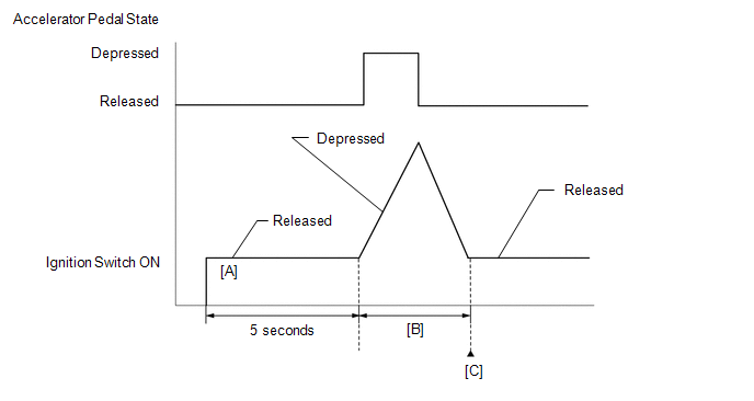
- Turn the ignition switch to ON [A].
- Turn the GTS on.
- Wait for 5 seconds after turning the ignition switch to ON.
- Operate the accelerator pedal in accordance with the following procedure [B].
- Enter the following menus: Powertrain / Engine / Data List / Accelerator Position Sensor No.1 Voltage % and Accelerator Position Sensor No.2 Voltage %.
- Slowly depress the accelerator pedal until Accelerator Position Sensor No.1 Voltage % is approximately 30% and Accelerator Position Sensor No.2 Voltage % is approximately 46%, then slowly release the accelerator pedal.
- Enter the following menus: Powertrain / Engine / Trouble Codes [C].
- Read the pending DTCs.
HINT:
- If a pending DTC is output, the system is malfunctioning.
- If a pending DTC is not output, perform the following procedure.
- Enter the following menus: Powertrain / Engine / Utility / All Readiness.
- Proceed to the next screen and enter the DTC to be checked.
- Check the DTC judgment result.
GTS Display
Description
NORMAL
- DTC judgment completed
- System normal
ABNORMAL
- DTC judgment completed
- System abnormal
INCOMPLETE
- DTC judgment not completed
- Perform driving pattern after confirming DTC enabling conditions
HINT:
- If the judgment result is NORMAL, the system is normal.
- If the judgment result is ABNORMAL, the system is malfunctioning.
- If the judgment result is INCOMPLETE, perform steps [B] through [C] again.
- [A] to [C]: Normal judgment procedure.
The normal judgment procedure is used to complete DTC judgment and also used when clearing permanent DTCs.
- When clearing the permanent DTCs, do not disconnect the cable from the auxiliary battery terminal or attempt to clear the DTCs during this procedure, as doing so will clear the universal trip and normal judgment histories.
FAIL-SAFE
When these DTCs are stored, the ECM enters fail-safe mode. If either of the 2 sensor circuits malfunctions, the ECM limits the engine output. If both of the circuits malfunction, the ECM regards the accelerator pedal as being released. As a result, the throttle valve is closed and the engine idles.
Fail-safe mode continues until a pass condition is detected, and the ignition switch is turned off.
WIRING DIAGRAM
Refer to DTC P212012.
Click here
CAUTION / NOTICE / HINT
HINT:
Read Freeze Frame Data using the GTS. The ECM records vehicle and driving condition information as Freeze Frame Data the moment a DTC is stored. When troubleshooting, Freeze Frame Data can help determine if the vehicle was moving or stationary, if the engine was warmed up or not, if the air fuel ratio was lean or rich, and other data from the time the malfunction occurred.
PROCEDURE
| 1. |
CHECK ANY OTHER DTCS OUTPUT (IN ADDITION TO DTC P21201C OR P212099) |
(a) Read the DTCs.
Powertrain > Engine > Trouble Codes|
Result | Proceed to |
|---|---|
|
DTC P21201C or P212099 is output |
A |
| DTC P21201C or P212099 and other DTCs are output |
B |
HINT:
If any DTCs other than P21201C or P212099 are output, troubleshoot those DTCs first.
| B |
.gif) | GO TO DTC CHART |
|
.gif)
| 2. |
READ VALUE USING GTS (ACCELERATOR POSITION SENSOR NO. 1 VOLTAGE AND ACCELERATOR POSITION SENSOR NO. 2 VOLTAGE) |
|
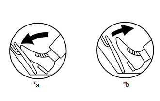
*a | Fully Depressed |
|
*b | Fully Released |
(a) Enter the following menus.
Powertrain > Engine > Data List|
Tester Display |
|---|
| Accelerator Position Sensor No.1 Voltage |
|
Accelerator Position Sensor No.2 Voltage |
(b) Read the value displayed on the GTS.
Standard Voltage:
|
Accelerator Pedal Operation |
Accelerator Position Sensor No.1 Voltage |
Accelerator Position Sensor No.2 Voltage |
Difference between Accelerator Position Sensor No.1 Voltage and Accelerator Position Sensor No.2 Voltage |
|---|---|---|---|
|
Fully Released | 0.5 to 1.1 V |
1.2 to 2.0 V |
More than 0.02 V |
|
Fully Depressed | 2.6 to 4.5 V |
3.4 to 4.75 V |
| OK | | CHECK FOR INTERMITTENT PROBLEMS |
| NG | | REPLACE ACCELERATOR PEDAL SENSOR ASSEMBLY |
READ NEXT:
 Throttle/Pedal Position Sensor/Switch "D" Circuit Intermittent (P21201F,P21251F)
DESCRIPTION HINT: These DTCs relate to the accelerator pedal position sensor.
Refer to DTC P212012. Click here
DTC No. Detection Item
DTC Detection Condition Trouble Area
MIL
Throttle/Pedal Position Sensor/Switch "E" Circuit Short to Battery (P212512)
DESCRIPTION HINT: These DTCs relate to the accelerator pedal position sensor.
Refer to DTC P212012. Click here
DTC No. Detection Item
DTC Detection Condition Trouble Area
MIL
Throttle/Pedal Position Sensor/Switch "E" Circuit Short to Ground or Open (P212514)
DESCRIPTION HINT: These DTCs relate to the accelerator pedal position sensor.
Refer to DTC P212012. Click here
DTC No. Detection Item
DTC Detection Condition Trouble Area
MIL
SEE MORE:
 Ultrasonic Sensor (Front Right Corner) Missing Message (C1AE487)
DESCRIPTION
This DTC is output when an open circuit or short occurs in the
communication line between a front corner ultrasonic sensor (FR sensor) and the
front center ultrasonic sensor (FRC sensor), or when a malfunction occurs in a front
corner ultrasonic sensor (FR sensor) on the front.
Cylinder 1 Injector Circuit Range/Performance (P02EE00,P02EF00,P02F000,P02F100)
DESCRIPTION By using Partial Lift Fuel Injection Control to spray fuel before the needle inside each direct fuel injector assembly has fully opened, the injection of fuel by the direct fuel injector assembly can be precisely controlled at partial lift. Due to the influence on the injected fuel volum
