Toyota Corolla Cross: Terminals Of Ecu
TERMINALS OF ECU

|
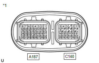
*1 | Inverter with Converter Assembly |
HINT:
Since the inverter with converter assembly uses waterproof connectors, the voltage and waveforms cannot be inspected directly. Standard voltage readings and waveforms are indicated for reference only.
Inverter with Converter Assembly|
Connector code | Terminal No. |
Symbol | Terminal Description |
|---|---|---|---|
|
A187 | 1 |
IGC1 | Motor generator control ECU (MG ECU) power source |
|
2 | NE |
Crankshaft position sensor signal | |
|
3 | CALH |
CAN communication signal | |
|
4 | GND1 |
Ground | |
|
5 | CANH |
CAN communication signal | |
|
6 | CANL |
CAN communication signal | |
|
7 | RRFG |
Rear motor resolver reference signal ground | |
|
8 | RRF |
Rear motor resolver reference signal | |
|
9 | IGC2 |
Motor generator control ECU (MG ECU) power source | |
|
10 | GI |
Camshaft position sensor signal | |
|
11 | CALL |
CAN communication signal | |
|
12 | GND2 |
Ground | |
|
13 | CADH |
CAN communication signal | |
|
14 | CADL |
CAN communication signal | |
|
15 | DRN7 |
Ground for shield | |
|
16 | - |
- | |
| 17 |
- | - | |
|
18 | - |
- | |
| 19 |
DRN5 | Ground for shield | |
|
20 | DRN1 |
Ground for shield | |
|
21 | - |
- | |
| 22 |
- | - | |
|
23 | RCSG |
Rear motor resolver signal ground | |
|
24 | RCS |
Rear motor resolver signal | |
|
25 | - |
- | |
| 26 |
HSDN | MG shutdown signal | |
|
27 | DRN2 |
Ground for shield | |
|
28 | - |
- | |
| 29 |
HMCH | Communication signal | |
|
30 | HMCL |
Communication signal | |
|
31 | RSNG |
Rear motor resolver signal ground | |
|
32 | RSN |
Rear motor resolver signal | |
|
C140 | 1 |
MRF | Motor resolver reference signal |
|
2 | MRFG |
Motor resolver reference signal ground | |
|
3 | GRF |
Generator resolver reference signal | |
|
4 | GRFG |
Generator resolver reference signal ground | |
|
5 | MMT |
Motor temperature sensor | |
|
6 | DRN6 |
Ground for shield | |
|
7 | DRN3 |
Ground for shield | |
|
8 | MMTG |
Motor temperature sensor ground | |
|
9 | MSN |
Motor resolver signal | |
|
10 | MSNG |
Motor resolver signal ground | |
|
11 | TTAG |
Transmission fluid temperature sensor ground | |
|
12 | GSNG |
Generator resolver signal ground | |
|
13 | GSN |
Generator resolver signal | |
|
14 | GMTG |
Generator temperature sensor ground | |
|
15 | MCS |
Motor resolver signal | |
|
16 | MCSG |
Motor resolver signal ground | |
|
17 | TTA |
Transmission fluid temperature sensor | |
|
18 | GCSG |
Generator resolver signal ground | |
|
19 | GCS |
Generator resolver signal | |
|
20 | GMT |
Generator temperature sensor |
NOTICE:
Do not measure the voltage or waveform on the sealed side of the inverter with converter assembly connector. Doing so may damage the connector because the connector is waterproof.


