Toyota Corolla Cross: System Diagram
SYSTEM DIAGRAM
 Communication Table
 |
Transmitting ECU / Parts (Transmitter) |
Receiving ECU / Parts (Receiver) |
Signal | Communication Method |
|---|---|---|---|
|
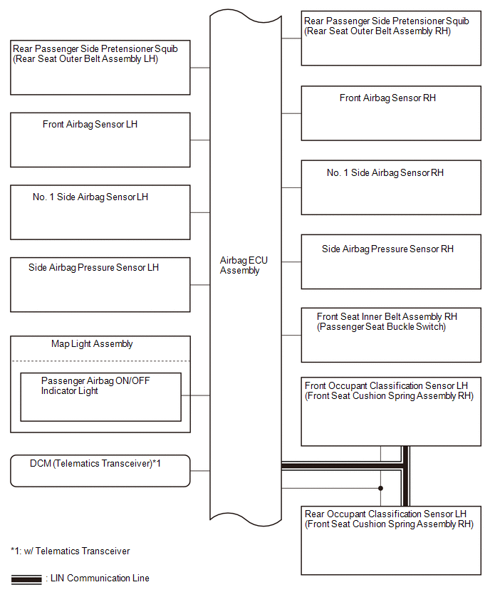
Front Airbag Sensor |
Airbag ECU Assembly | Front collision G signal |
Direct line |
|
No. 1 Side Airbag Sensor |
Side collision G signal | ||
|
Side Airbag Pressure Sensor |
Side collision P signal | ||
|
Passenger Seat Buckle Switch (Front Seat Inner Belt Assembly RH) |
Passenger seat belt fastened signal | ||
|
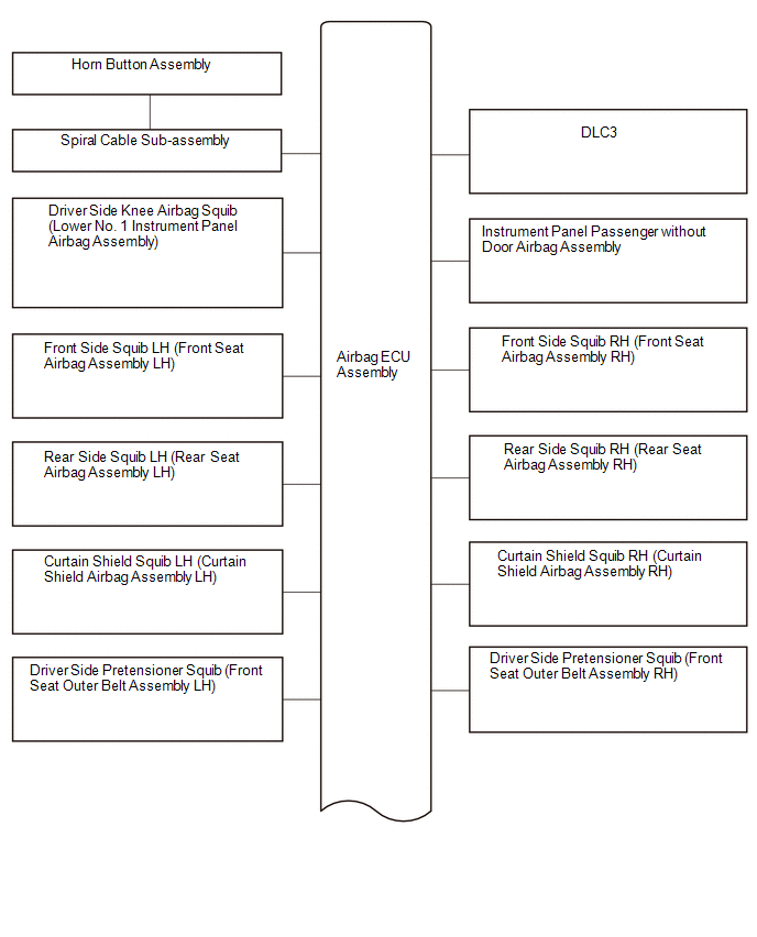
Airbag ECU Assembly | Horn Button Assembly |
Ignition signal |
Direct line |
|
Instrument Panel Passenger without Door Airbag Assembly | |||
|
Lower No. 1 Instrument Panel Airbag Assembly | |||
|
Front Seat Airbag Assembly | |||
|
Rear Seat Airbag Assembly | |||
|
Curtain Shield Airbag Assembly | |||
|
Front Seat Outer Belt Assembly | |||
|
Passenger Airbag ON Indicator (Map Light Assembly) |
| ||
| Passenger Airbag OFF Indicator (Map Light Assembly) |
| ||
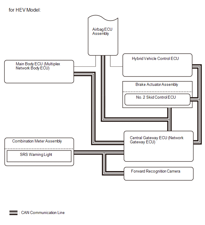
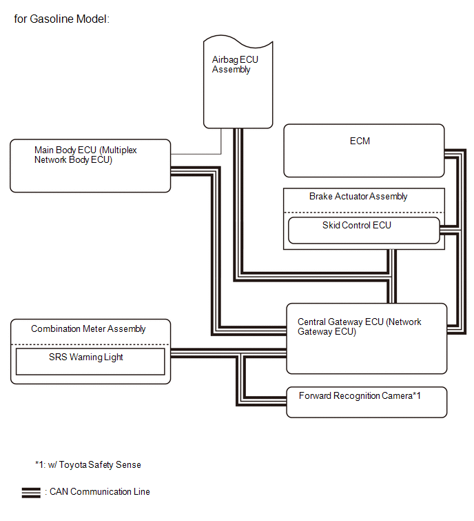
| Main Body ECU (Multiplex Network Body ECU) |
Collision detection signal (for door lock release) | ||
|
DCM (Telematics Transceiver)*1 | Collision detection signal (for mayday output) | ||
|
Airbag ECU Assembly | Hybrid Vehicle Control ECU*2 |
Collision detection signal (for hybrid high voltage release) |
CAN |
| ECM*3 |
Collision detection signal (for fuel cut) | ||
|
Skid Control ECU (Brake Actuator Assembly) | Collision detection signal (for secondary collision brake) | ||
|
Combination Meter Assembly |
| ||
| Main Body ECU (Multiplex Network Body ECU) |
Interior light illumination request signal | ||
|
Forward Recognition Camera*4 |
Airbag ECU Assembly | Front PCS information |
CAN |
- *1: w/ Telematics Transceiver
- *2: for HEV Model
- *3: for Gasoline Model
- *4: w/ Toyota Safety Sense


