Toyota Corolla Cross: Sliding Roof Switch Assembly
Removal
REMOVAL
CAUTION / NOTICE / HINT
COMPONENTS (REMOVAL)

|
Procedure | Part Name Code |
.png) |
.png) |
.png) |
|
1 | MAP LIGHT ASSEMBLY |
81260A |
.gif) |
- | - |
PROCEDURE
1. REMOVE MAP LIGHT ASSEMBLY
Click here
.gif)
Inspection
INSPECTION
PROCEDURE
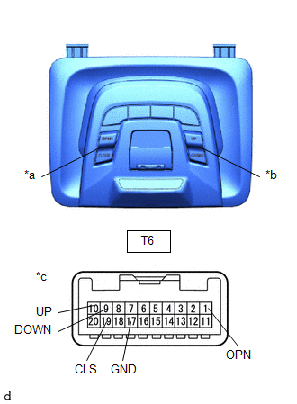
1. INSPECT SLIDING ROOF SWITCH (MAP LIGHT ASSEMBLY)
(a) Check the sliding roof switch.
| (1) Measure the resistance according to the value(s) in the table below.
Standard Resistance: |
Tester Connection | Condition |
Specified Condition | |
T6-10 (UP) - T6-17 (GND) |
UP switch pressed |
Below 100 Ω | |
T6-10 (UP) - T6-17 (GND) |
UP switch not pressed |
1 kΩ or higher | |
T6-9 (DOWN) - T6-17 (GND) |
DOWN switch pressed |
Below 100 Ω | |
T6-9 (DOWN) - T6-17 (GND) |
DOWN switch not pressed |
1 kΩ or higher | |
T6-1 (OPN) - T6-17 (GND) |
OPEN switch pressed |
Below 100 Ω | |
T6-1 (OPN) - T6-17 (GND) |
OPEN switch not pressed |
1 kΩ or higher | |
T6-19 (CLS) - T6-17 (GND) |
CLOSE switch pressed |
Below 100 Ω | |
T6-19 (CLS) - T6-17 (GND) |
CLOSE switch not pressed |
1 kΩ or higher | If the result is not as specified, replace the sliding roof switch (map light assembly). |
 |
|
*a | Sliding Roof Switch | |
*b | Tilt Switch | |
*c | Component without harness connected
(Sliding Roof Switch (Map Light Assembly)) | | |
Installation
INSTALLATION
CAUTION / NOTICE / HINT
COMPONENTS (INSTALLATION)

|
Procedure | Part Name Code |
.png) |
.png) |
.png) |
|
1 | MAP LIGHT ASSEMBLY |
81260A | - |
- | - |
PROCEDURE
1. INSTALL MAP LIGHT ASSEMBLY
READ NEXT:
PARTS LOCATION ILLUSTRATION
*1 SLIDING ROOF ECU (SLIDING ROOF DRIVE GEAR SUB-ASSEMBLY)
*2 SLIDING ROOF SWITCH (MAP LIGHT ASSEMBLY)
*3 FRONT DOOR COURTESY LIGHT SWITCH ASSEMBLY
SEE MORE:
INSTALLATION CAUTION / NOTICE / HINT COMPONENTS (INSTALLATION)
Procedure Part Name Code
1 NO. 2 INSTRUMENT PANEL WIRE
82142
- -
2 INSTRUMENT PANEL PASSENGER AIRBAG ASSEMBLY
73960A -
- -
3 INSTRUMENT PAN
DTC SUMMARY MALFUNCTION DESCRIPTION The hybrid vehicle control ECU detects a VH sensor malfunction.
The cause of this malfunction may be one of the following: Inverter voltage sensor internal circuit malfunction
Voltage sensor malfunction
Motor generator control ECU (MG ECU) malfuncti

.png)
.png)
.png)
.gif)

.png)
.png)
.png)


