Toyota Corolla Cross: Sliding Roof does not Move by Operating Sliding Roof Control Switch
DESCRIPTION
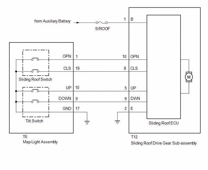
The sliding roof ECU (sliding roof drive gear sub-assembly) receives slide and tilt signals and operates its built-in motor when the sliding roof switch (map light assembly) is operated.
WIRING DIAGRAM
CAUTION / NOTICE / HINT
NOTICE:
- Inspect the fuses for circuits related to this system before performing the following procedure.
- If the sliding roof ECU (sliding roof drive gear sub-assembly) is removed and reinstalled or replaced, the sliding roof ECU (sliding roof drive gear sub-assembly) must be initialized.
Click here
.gif)
- If a sliding roof ECU (sliding roof drive gear sub-assembly) DTC is output, first perform troubleshooting for the sliding roof ECU (sliding roof drive gear sub-assembly) DTC.
PROCEDURE
|
1. | PERFORM ACTIVE TEST USING GTS (SLIDING ROOF) |
(a) Perform the Active Test according to the display on the GTS.
Body Electrical > Main Body > Active Test|
Tester Display | Measurement Item |
Control Range | Diagnostic Note |
|---|---|---|---|
|
Sliding Roof Open | Sliding roof open activate |
OFF/ON | - |
|
Sliding Roof Close | Sliding roof close activate |
OFF/ON | - |
|
Tester Display |
|---|
| Sliding Roof Open |
|
Tester Display |
|---|
| Sliding Roof Close |
OK:
Slide roof is operated using GTS.
| NG | .gif) | GO TO STEP 5 |
|
.gif)
| 2. |
READ VALUE USING GTS |
(a) Read the Data List according to the display on the GTS.
Body Electrical > Main Body > Data List|
Tester Display | Measurement Item |
Range | Normal Condition |
Diagnostic Note |
|---|---|---|---|---|
|
Roof OPEN Switch | OPEN switch signal |
OFF or ON | OFF: OPEN switch not pressed ON: OPEN switch pressed |
- |
| Roof CLOSE Switch |
CLOSE switch signal | OFF or ON |
OFF: CLOSE switch not pressed ON: CLOSE switch pressed |
- |
| Roof UP Switch |
UP switch signal | OFF or ON |
OFF: UP switch not pressed ON: UP switch pressed |
- |
| Roof DOWN Switch |
DOWN switch signal | OFF or ON |
OFF: DOWN switch not pressed ON: DOWN switch pressed |
- |
|
Tester Display |
|---|
| Roof OPEN Switch |
|
Roof CLOSE Switch |
|
Roof UP Switch |
|
Roof DOWN Switch |
OK:
The GTS display changes according to the operation of each switch as shown in the table.
| OK | | REPLACE SLIDING ROOF ECU (SLIDING ROOF DRIVE GEAR SUB-ASSEMBLY) |
|
| 3. |
INSPECT SLIDING ROOF SWITCH (MAP LIGHT ASSEMBLY) |
Click here
| NG | | REPLACE SLIDING ROOF SWITCH (MAP LIGHT ASSEMBLY) |
|
| 4. |
CHECK HARNESS AND CONNECTOR (SLIDING ROOF ECU (SLIDING ROOF DRIVE GEAR SUB-ASSEMBLY) - SLIDING ROOF SWITCH (MAP LIGHT ASSEMBLY) AND BODY GROUND) |
(a) Disconnect the T6 sliding roof switch (map light assembly) connector.
(b) Disconnect the T12 sliding roof ECU (sliding roof drive gear sub-assembly) connector.
(c) Measure the resistance according to the value(s) in the table below.
Standard Resistance:
|
Tester Connection | Condition |
Specified Condition |
|---|---|---|
|
T12-8 (CLS) - T6-19 (CLS) |
Always | Below 1 Ω |
|
T12-8 (CLS) or T6-19 (CLS) - Body ground |
Always | 10 kΩ or higher |
|
T12-10 (OPN) - T6-1 (OPN) |
Always | Below 1 Ω |
|
T12-10 (OPN) or T6-1 (OPN) - Body ground |
Always | 10 kΩ or higher |
|
T12-9 (DWN) - T6-9 (DOWN) |
Always | Below 1 Ω |
|
T12-9 (DWN) or T6-9 (DOWN) - Body ground |
Always | 10 kΩ or higher |
|
T12-5 (UP) - T6-10 (UP) |
Always | Below 1 Ω |
|
T12-5 (UP) or T6-10 (UP) - Body ground |
Always | 10 kΩ or higher |
|
T6-17 (GND) - Body ground |
Always | Below 1 Ω |
|
T12-2 (E) - Body ground |
Always | Below 1 Ω |
| OK | | REPLACE SLIDING ROOF ECU (SLIDING ROOF DRIVE GEAR SUB-ASSEMBLY) |
| NG | | REPAIR OR REPLACE HARNESS OR CONNECTOR |
| 5. |
CHECK HARNESS AND CONNECTOR (SLIDING ROOF ECU (SLIDING ROOF DRIVE GEAR SUB-ASSEMBLY) - AUXILIARY BATTERY AND BODY GROUND) |
(a) Disconnect the T12 sliding roof ECU (sliding roof drive gear sub-assembly) connector.
(b) Measure the voltage according to the value(s) in the table below.
Standard Voltage:
|
Tester Connection | Switch Condition |
Specified Condition |
|---|---|---|
|
T12-1 (B) - Body ground |
Ignition switch off | 11 to 14 V |
(c) Measure the resistance according to the value(s) in the table below.
Standard Resistance:
|
Tester Connection | Condition |
Specified Condition |
|---|---|---|
|
T12-2 (E) - Body ground |
Always | Below 1 Ω |
| OK | | REPLACE SLIDING ROOF ECU (SLIDING ROOF DRIVE GEAR SUB-ASSEMBLY) |
| NG | | REPAIR OR REPLACE HARNESS OR CONNECTOR |


