Toyota Corolla Cross: Fuel Rail Pressure Sensor (Low) / Fuel Rail Pressure Sensor "B" Circuit Short to Ground (P107A11)
DESCRIPTION
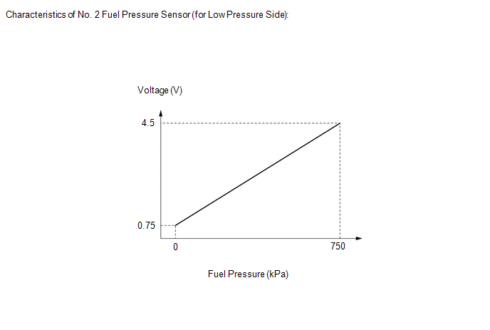
The No. 2 fuel pressure sensor (for low pressure side) replaces the fuel pressure with electrical signals and outputs them to the ECM. The ECM controls the optimal fuel pressure for the operation conditions to reduce the fuel pump power consumption and improve fuel economy.
|
DTC No. | Detection Item |
DTC Detection Condition | Trouble Area |
MIL | Note |
|---|---|---|---|---|---|
|
P107A11 | Fuel Rail Pressure Sensor (Low) / Fuel Rail Pressure Sensor "B" Circuit Short to Ground |
The No. 2 fuel pressure sensor (for low pressure side) output voltage is less than 0.43 V for 3 seconds or more (1 trip detection logic). |
| Comes on |
|
HINT:
When a DTC is output, check the Data List item "Fuel Pressure (Low) / Fuel Pressure 2" using the GTS.
Click here .gif)
|
DTC No. | Fuel Pressure (Low) / Fuel Pressure 2 |
Malfunction |
|---|---|---|
| P107A11 |
Approximately 0 kPag |
|
If the Data List displays a normal value, the normal value may be due to a temporary recovery from the malfunction condition. Check for intermittent problems.
MONITOR DESCRIPTION
This DTC is stored if the No. 2 fuel pressure sensor (for low pressure side) output voltage is out of the standard range due to an open or short in the sensor circuit.
MONITOR STRATEGY
|
Related DTCs | P107C: Fuel rail pressure sensor range check (Low voltage) |
|
Required Sensors/Components (Main) | Fuel pressure sensor (for low pressure side) |
|
Required Sensors/Components (Related) |
- |
| Frequency of Operation |
Continuous |
| Duration |
3 seconds |
| MIL Operation |
Immediate |
| Sequence of Operation |
None |
TYPICAL ENABLING CONDITIONS
|
Monitor runs whenever the following DTCs are not stored |
None |
| All of the following conditions are met |
- |
| Auxiliary battery voltage |
8 V or higher |
| Ignition switch |
ON |
| Time after engine start |
2 seconds or more |
TYPICAL MALFUNCTION THRESHOLDS
|
Fuel rail pressure sensor voltage | Less than 0.43 V |
CONFIRMATION DRIVING PATTERN
HINT:
- After repair has been completed, clear the DTC and then check that the vehicle has returned to normal by performing the following All Readiness check procedure.
Click here
- When clearing the permanent DTCs, refer to the "CLEAR PERMANENT DTC" procedure.
Click here
- Connect the GTS to the DLC3.
- Turn the ignition switch to ON.
- Turn the GTS on.
- Clear the DTCs (even if no DTCs are stored, perform the clear DTC procedure).
- Turn the ignition switch off and wait for at least 30 seconds.
- Turn the ignition switch to ON.
- Turn the GTS on.
- Put the engine in Inspection Mode (Maintenance Mode).
Click here
- Start the engine.
- Idle the engine for 10 seconds or more [A].
- Enter the following menus: Powertrain / Engine / Trouble Codes [B].
- Read the pending DTCs.
HINT:
- If a pending DTC is output, the system is malfunctioning.
- If a pending DTC is not output, perform the following procedure.
- Enter the following menus: Powertrain / Engine / Utility / All Readiness.
- Input the DTC: P107A11.
- Check the DTC judgment result.
GTS Display
Description
NORMAL
- DTC judgment completed
- System normal
ABNORMAL
- DTC judgment completed
- System abnormal
INCOMPLETE
- DTC judgment not completed
- Perform driving pattern after confirming DTC enabling conditions
HINT:
- If the judgment result is NORMAL, the system is normal.
- If the judgment result is ABNORMAL, the system has a malfunction.
- If the judgment result is INCOMPLETE, perform steps [A] through [B] again.
- [A] to [B]: Normal judgment procedure.
The normal judgment procedure is used to complete DTC judgment and also used when clearing permanent DTCs.
- When clearing the permanent DTCs, do not disconnect the cable from the auxiliary battery terminal or attempt to clear the DTCs during this procedure, as doing so will clear the universal trip and normal judgment histories.
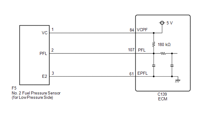
WIRING DIAGRAM
CAUTION / NOTICE / HINT
NOTICE:
- Vehicle Control History may be stored in the hybrid vehicle control ECU assembly if the engine is malfunctioning. Certain vehicle condition information is recorded when Vehicle Control History is stored. Reading the vehicle conditions recorded in both the freeze frame data and Vehicle Control History can be useful for troubleshooting.
Click here
(Select Powertrain in Health Check and then check the time stamp data.)
- If any "Engine Malfunction" Vehicle Control History item has been stored in the hybrid vehicle control ECU assembly, make sure to clear it. However, as all Vehicle Control History items are cleared simultaneously, if any Vehicle Control History items other than "Engine Malfunction" are stored, make sure to perform any troubleshooting for them before clearing Vehicle Control History.
Click here
HINT:
Read Freeze Frame Data using the GTS. The ECM records vehicle and driving condition information as Freeze Frame Data the moment a DTC is stored. When troubleshooting, Freeze Frame Data can help determine if the vehicle was moving or stationary, if the engine was warmed up or not, if the air fuel ratio was lean or rich, and other data from the time the malfunction occurred.
PROCEDURE
| 1. |
CHECK HARNESS AND CONNECTOR |
|
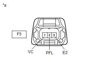
*a | Front view of wire harness connector (to No. 2 Fuel Pressure Sensor (for Low Pressure Side)) |
HINT:
Make sure that the connector is properly connected. If it is not, securely connect it and check for DTCs again.
(a) Disconnect the No. 2 fuel pressure sensor (for low pressure side) connector.
(b) Turn the ignition switch to ON.
(c) Measure the voltage according to the value(s) in the table below.
Standard Voltage:
|
Tester Connection | Condition |
Specified Condition |
|---|---|---|
|
F5-1 (VC) - F5-3 (E2) |
Ignition switch ON | 4.5 to 5.5 V |
|
F5-2 (PFL) - F5-3 (E2) |
Ignition switch ON | 4.4 to 5.6 V |
(d) Turn the ignition switch off and wait for at least 30 seconds.
(e) Measure the resistance according to the value(s) in the table below.
Standard Resistance:
|
Tester Connection | Condition |
Specified Condition |
|---|---|---|
|
F5-1 (VC) - F5-2 (PFL) |
Ignition switch off | 171 to 189 kΩ |
HINT:
Perform "Inspection After Repair" after replacing the No. 2 fuel pressure sensor (for low pressure side).
Click here
| OK | .gif) | REPLACE NO. 2 FUEL PRESSURE SENSOR (FOR LOW PRESSURE SIDE) |
|
.gif)
| 2. |
CHECK HARNESS AND CONNECTOR (NO. 2 FUEL PRESSURE SENSOR (FOR LOW PRESSURE SIDE) - ECM) |
(a) Disconnect the No. 2 fuel pressure sensor (for low pressure side) connector.
(b) Disconnect the ECM connector.
(c) Measure the resistance according to the value(s) in the table below.
Standard Resistance:
|
Tester Connection | Condition |
Specified Condition |
|---|---|---|
|
F5-1 (VC) - C139-84 (VCPF) |
Always | Below 1 Ω |
|
F5-2 (PFL) or C139-107 (PFL) - Body ground and other terminals |
Always | 10 kΩ or higher |
| OK | | REPLACE ECM |
| NG | | REPAIR OR REPLACE HARNESS OR CONNECTOR |
READ NEXT:
 Fuel Rail Pressure Sensor (Low) / Fuel Rail Pressure Sensor "B" Circuit Short to Battery or Open (P107A15)
DESCRIPTION Refer to DTC P107A11. Click here
DTC No. Detection Item
DTC Detection Condition Trouble Area
MIL Note
P107A15 Fuel Rail Pressure Sensor (Low) / Fuel Rai
Fuel Rail Pressure Sensor (Low) Signal Stuck in Range (P107A2A,P107A64)
DESCRIPTION Refer to DTC P107A11. Click here
DTC No. Detection Item
DTC Detection Condition Trouble Area
MIL Note
P107A2A Fuel Rail Pressure Sensor (Low) Signal Stu
Control Module Internal Temperature Sensor/Intake Air Temperature Sensor Signal Compare Failure (P111C62)
DESCRIPTION The engine has an ECM internal temperature sensor and intake air temperature sensor.
The resistance of a thermistor within the ECM internal temperature sensor and intake air temperature
SEE MORE:
 Lost Communication with Front Panel LIN Missing Message (B14B287)
DESCRIPTION The air conditioning control assembly communicates with the air conditioning amplifier assembly via LIN communication.
If a malfunction occurs in the LIN communication system, the air conditioning amplifier assembly will not operate, even if the air conditioning control assembly is ope
Driver Side Door Entry Unlock Function does not Operate
DESCRIPTION If the entry unlock function does not operate for the driver door only, but the entry lock function operates, the request code is being transmitted properly from the driver door. In this case, there may be a problem related to the unlock sensor (connection between the certification ECU (
