Toyota Corolla Cross: Removal
REMOVAL
CAUTION / NOTICE / HINT
COMPONENTS (REMOVAL)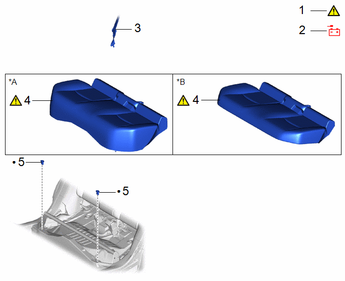
|
Procedure | Part Name Code |
.png) |
.png) |
 |
|---|---|---|---|---|---|
|
1 | PRECAUTION |
- |
|
- | - |
|
2 | CABLE FROM NEGATIVE AUXILIARY BATTERY TERMINAL |
- | - |
- | - |
|
3 | REAR CENTER SEAT OUTER BELT ASSEMBLY |
- | - |
- | - |
|
4 | BENCH TYPE REAR SEAT CUSHION ASSEMBLY |
- |
|
- | - |
|
5 | REAR SEAT CUSHION LOCK HOOK |
72693 | - |
- | - |
|
*A | for Gasoline Model |
*B | for HEV Model |
|
● | Non-reusable part |
- | - |
|
Procedure | Part Name Code |
|
|
| |
|---|---|---|---|---|---|
|
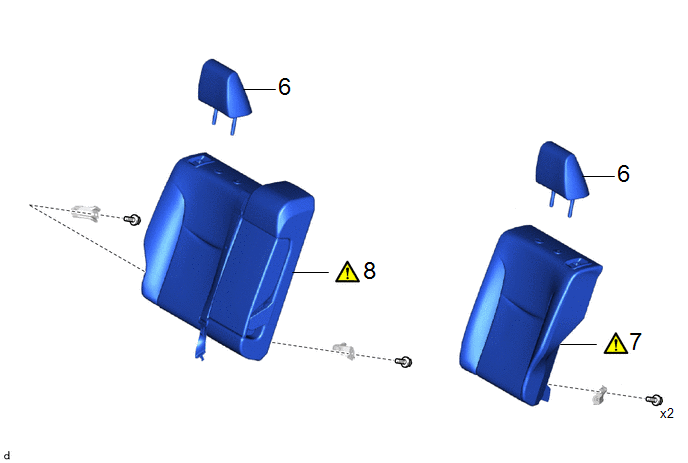
6 | REAR SEAT HEADREST ASSEMBLY |
71940A | - |
- | - |
|
7 | REAR SEATBACK ASSEMBLY LH |
- |
|
- | - |
|
8 | REAR SEATBACK ASSEMBLY RH |
- |
|
- | - |
|
Procedure | Part Name Code |
|
|
| |
|---|---|---|---|---|---|
|
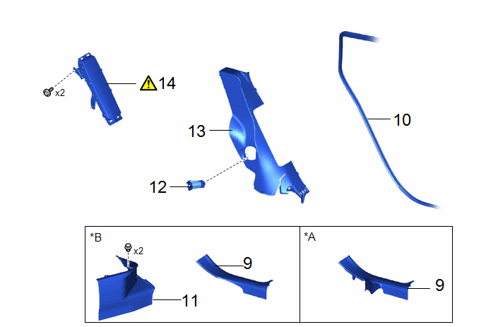
9 | REAR DOOR SCUFF PLATE LH |
67918A | - |
- | - |
|
10 | REAR DOOR OPENING TRIM WEATHERSTRIP |
62332A | - |
- | - |
|
11 | REAR UNDER SIDE COVER LH |
76974E | - |
- | - |
|
12 | REAR SEAT BACK HINGE SUB-ASSEMBLY LH |
71304C | - |
- | - |
|
13 | REAR SEAT SIDE GARNISH LH |
62552F | - |
- | - |
|
14 | REAR SEAT SIDE AIRBAG ASSEMBLY |
- |
|
- | - |
|
*A | for Gasoline Model |
*B | for HEV Model |
CAUTION / NOTICE / HINT
The necessary procedures (adjustment, calibration, initialization or registration) that must be performed after parts are removed and installed, or replaced during rear seat side airbag assembly removal/installation are shown below.
NOTICE:
After the ignition switch is turned off, the radio and display receiver assembly records various types of memory and settings. As a result, after turning the ignition switch off, make sure to wait at least 120 seconds before disconnecting the cable from the negative (-) auxiliary battery terminal.
HINT:
When the cable is disconnected/reconnected to the auxiliary battery terminal, systems temporarily stop operating. However, each system has a function that completes learning the first time the system is used.
- Learning completes when vehicle is driven
Effect/Inoperative Function When Necessary Procedures are not Performed
Necessary Procedures
Link
*A: for Gasoline Model Front Camera System
Drive the vehicle straight ahead at 15 km/h (10 mph) or more for 1 second or more.
.gif)
Stop and start system*A
Drive the vehicle until stop and start control is permitted (approximately 5 to 60 minutes)
- Learning completes when vehicle is operated normally
Effect/Inoperative Function When Necessary Procedures are not Performed
Necessary Procedures
Link
Power door lock control system
- Back door opener
Perform door unlock operation with door control switch or electrical key transmitter sub-assembly switch.
Power back door system
Fully close the back door by hand.
HINT:
Initialization is not necessary if the above procedures are performed while the back door is closed.
Air conditioning system
After the ignition switch is turned to ON, the servo motor standard position is recognized.
-
HINT:
- Use the same procedure for the RH side and LH side.
- The following procedure is for the LH side.
PROCEDURE
1. PRECAUTION
|
|
CAUTION: Be sure to read Precaution thoroughly before servicing. .png) NOTICE: After turning the ignition switch off, waiting time may be required before disconnecting the cable from the negative (-) auxiliary battery terminal. |
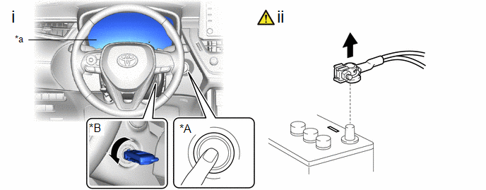
2. DISCONNECT CABLE FROM NEGATIVE AUXILIARY BATTERY TERMINAL
|
|
CAUTION:
|
.png)
- for Gasoline Model
Click here
- for HEV Model
Click here
3. DISCONNECT REAR CENTER SEAT OUTER BELT ASSEMBLY
|
|
|
4. REMOVE BENCH TYPE REAR SEAT CUSHION ASSEMBLY
|
|
|
5. REMOVE REAR SEAT CUSHION LOCK HOOK
Click here
6. REMOVE REAR SEAT HEADREST ASSEMBLY
- for RH Side
Click here
- for LH Side
Click here
7. REMOVE REAR SEATBACK ASSEMBLY LH
|
|
|
8. REMOVE REAR SEATBACK ASSEMBLY RH
|
|
|
9. REMOVE REAR DOOR SCUFF PLATE LH
Click here
10. DISCONNECT REAR DOOR OPENING TRIM WEATHERSTRIP
Click here
11. REMOVE REAR UNDER SIDE COVER LH (for HEV Model)
Click here
12. REMOVE REAR SEAT BACK HINGE SUB-ASSEMBLY LH
Click here
13. REMOVE REAR SEAT SIDE GARNISH LH
Click here
14. REMOVE REAR SEAT SIDE AIRBAG ASSEMBLY
|
|
CAUTION:
|
|
*A | w/ Smart Key System |
*B | w/o Smart Key System |
|
*a | illumination off |
- | - |
(1) Check that the ignition switch is off.
(2) Check that the cable is disconnected from the negative (-) auxiliary battery terminal.
CAUTION:
- Wait at least 90 seconds after disconnecting the cable from the negative (-)auxiliary battery terminal to disable the SRS system.
- If the airbag deploys for any reason, it may cause a serious accident.
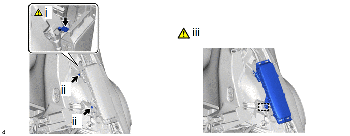
(1) Disconnect the airbag connector.
NOTICE:
When disconnecting any airbag connector, take care not to damage the airbag wire harness.
HINT:
Refer to How to Connect or Disconnect Airbag Connector:
Click here
(2) Remove the 2 bolts.
(3) Disengage the claw to remove the rear seat side airbag assembly.


