Toyota Corolla Cross: Removal
REMOVAL
CAUTION / NOTICE / HINT
COMPONENTS (REMOVAL)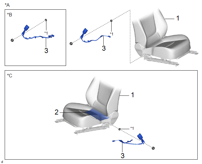
|
Procedure | Part Name Code |
.png) |
.png) |
 |
|---|---|---|---|---|---|
|
1 | FRONT SEAT ASSEMBLY |
- | - |
- | - |
|
2 | SEPARATE TYPE FRONT SEATBACK COVER |
71074S | - |
- | - |
|
3 | FRONT SEAT INNER BELT ASSEMBLY |
73240 | - |
- | - |
|
*A | for Driver Side Manual Seat |
*B | for Driver Side Power Seat |
|
*C | for Front Passenger Seat |
- | - |
|
*1 | FRONT SEAT BELT ANCHOR PLATE |
- | - |
|
Procedure | Part Name Code |
|
|
| |
|---|---|---|---|---|---|
|
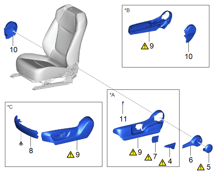
4 | VERTICAL ADJUSTING HANDLE |
72495 |
|
- | - |
|
5 | RECLINING HINGE COVER |
72552B |
|
- | - |
|
6 | RECLINING ADJUSTER RELEASE HANDLE |
72526 | - |
- | - |
|
7 | SEAT ADJUSTER COVER CAP |
71849 |
|
- | - |
|
8 | FRONT SEAT FRONT CUSHION SHIELD |
71868N | - |
- | - |
|
9 | FRONT SEAT CUSHION SHIELD |
71812D |
|
- | - |
|
10 | FRONT SEAT INNER CUSHION SHIELD |
71862 | - |
- | - |
|
11 | VERTICAL ADJUSTER BRACKET COVER |
72498B | - |
- | - |
|
*A | for Driver Side Manual Seat |
*B | for Front Passenger Seat |
|
*C | for Driver Side Power Seat |
- | - |
|
Procedure | Part Name Code |
|
|
| |
|---|---|---|---|---|---|
|
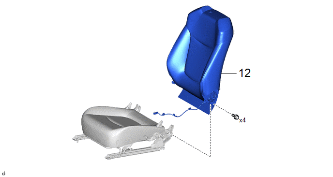
12 | SEPARATE TYPE FRONT SEATBACK ASSEMBLY |
- | - |
- | - |
|
Procedure | Part Name Code |
|
|
| |
|---|---|---|---|---|---|
|
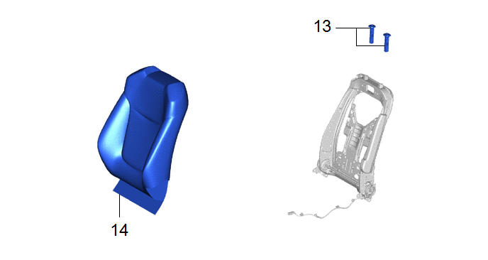
13 | FRONT SEAT HEADREST SUPPORT |
71931 | - |
- | - |
|
14 | SEPARATE TYPE FRONT SEATBACK COVER WITH PAD |
- | - |
- | - |
|
*A | w/ Heater |
- | - |
|
*1 | SEPARATE TYPE FRONT SEATBACK PAD |
- | - |
|
● | Non-reusable part |
- | - |
|
Procedure | Part Name Code |
|
|
| |
|---|---|---|---|---|---|
|
15 | FRONT SEAT AIRBAG ASSEMBLY |
73920A |
|
- | - |
|
● | Non-reusable part |
- | - |
CAUTION / NOTICE / HINT
CAUTION:
- Be sure to read precaution thoroughly before servicing.
Click here
.gif)
.png)
- Wear protective gloves. Sharp areas on the parts may injure your hands.
.png)
- There is risk of injury.
HINT:
When the cable is disconnected/reconnected to the auxiliary battery terminal, systems temporarily stop operating. However, each system has a function that completes learning the first time the system is used.
- Learning completes when vehicle is driven
Effect/Inoperative Function When Necessary Procedures are not Performed
Necessary Procedures
Link
*A: for Gasoline Model Front Camera System
Drive the vehicle straight ahead at 15 km/h (10 mph) or more for 1 second or more.
Stop and start system*A
Drive the vehicle until stop and start control is permitted (approximately 5 to 60 minutes)
- Learning completes when vehicle is operated normally
Effect/Inoperative Function When Necessary Procedures are not Performed
Necessary Procedures
Link
Power door lock control system
- Back door opener
Perform door unlock operation with door control switch or electrical key transmitter sub-assembly switch.
Power back door system
Fully close the back door by hand.
HINT:
Initialization is not necessary if the above procedures are performed while the back door is closed.
Air conditioning system
After the ignition switch is turned to ON, the servo motor standard position is recognized.
-
PROCEDURE
1. REMOVE FRONT SEAT ASSEMBLY
- for Manual Seat:
Click here
- for Power Seat:
Click here
2. DISCONNECT SEPARATE TYPE FRONT SEATBACK COVER
Click here
3. REMOVE FRONT SEAT INNER BELT ASSEMBLY
Click here
4. REMOVE VERTICAL ADJUSTING HANDLE (for Driver Side Manual Seat)
|
|
Click here |
5. REMOVE RECLINING HINGE COVER
|
|
Click here |
6. REMOVE RECLINING ADJUSTER RELEASE HANDLE
Click here
7. REMOVE SEAT ADJUSTER COVER CAP (for Driver Side Manual Seat)
|
|
Click here |
8. INSTALL FRONT SEAT FRONT CUSHION SHIELD (for Power Seat)
Click here
9. REMOVE FRONT SEAT CUSHION SHIELD
|
|
|
10. REMOVE FRONT SEAT INNER CUSHION SHIELD
- for Driver Side Manual Seat:
Click here
- for Front Passenger Side Manual Seat:
Click here
- for Power Seat:
Click here
11. REMOVE VERTICAL ADJUSTER BRACKET COVER (for Driver Side Manual Seat)
Click here
12. REMOVE SEPARATE TYPE FRONT SEATBACK ASSEMBLY
- for Manual Seat:
Click here
- for Power Seat:
Click here
13. REMOVE FRONT SEAT HEADREST SUPPORT
Click here
14. REMOVE SEPARATE TYPE FRONT SEATBACK COVER WITH PAD
Click here
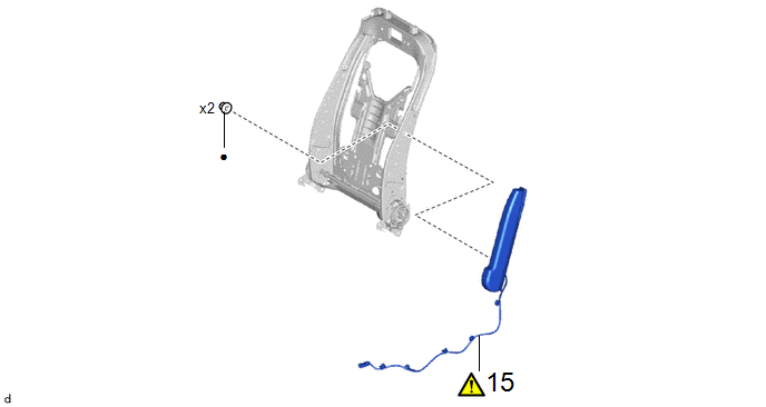
15. REMOVE FRONT SEAT AIRBAG ASSEMBLY
|
|
CAUTION:
 |

(1) Disengage the clamp.
(2) Remove the 2 nuts and front seat airbag assembly.
CAUTION:
- Do not reuse the nut.
- If the installation surface or surrounding area of the front seat airbag assembly is deformed or damaged, replace the front seatback frame sub-assembly LH with a new one.


