Toyota Corolla Cross: Left Frontal Restraints Sensor Value of Signal Protection Calculation Incorrect (B009083)
DESCRIPTION
|
DTC No. | Detection Item |
DTC Detection Condition | Trouble Area |
Warning Indicate | Test Mode / Check Mode |
|---|---|---|---|---|---|
|
B009083 | Left Frontal Restraints Sensor Value of Signal Protection Calculation Incorrect |
One of the following conditions is met:
|
| Comes on |
Does not apply to test/check mode |
|
Vehicle Condition | |||||||
|---|---|---|---|---|---|---|---|
|
Pattern 1 | Pattern 2 |
Pattern 3 | Pattern 4 |
Pattern 5 | Pattern 6 | ||
|
Diagnosis Condition | Ignition switch ON |
○ | ○ |
○ | ○ |
○ | ○ |
|
Malfunction Status | The airbag ECU assembly detects a line short circuit signal in the front airbag sensor LH circuit. |
○ | - |
- | - |
- | - |
|
The airbag ECU assembly detects an open circuit signal in the front airbag sensor LH circuit. |
- | ○ |
- | - |
- | - | |
|
The airbag ECU assembly detects a short circuit to ground signal in the front airbag sensor LH circuit. |
- | - |
○ | - |
- | - | |
|
The airbag ECU assembly detects a short circuit to B+ signal in the front airbag sensor LH circuit. |
- | - |
- | ○ |
- | - | |
|
Front airbag sensor LH malfunction |
- | - |
- | - |
○ | - | |
|
Airbag ECU assembly malfunction |
- | - |
- | - |
- | ○ | |
|
Detection Time | 2 seconds |
2 seconds | 2 seconds |
2 seconds | 2 seconds |
2 seconds | |
|
Number of Trips | 1 trip |
1 trip | 1 trip |
1 trip | 1 trip |
1 trip | |
HINT:
DTC will be output when conditions for either of the patterns in the table above are met.
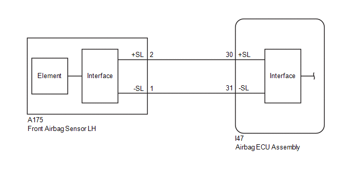
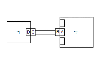
WIRING DIAGRAM
CAUTION / NOTICE / HINT
NOTICE:
After the ignition switch is turned off, there may be a waiting time before disconnecting the negative (-) battery terminal.
Click here .gif)
HINT:
When disconnecting and reconnecting the battery, there is an automatic learning function that completes learning when the respective system is used.
Click here
PROCEDURE
| 1. |
CHECK CONNECTION OF CONNECTORS |
(a) Turn the ignition switch off.
(b) Disconnect the cable from the negative (-) battery terminal.
CAUTION:
Wait at least 60 seconds after disconnecting the cable from the negative (-) battery terminal to disable the SRS system.
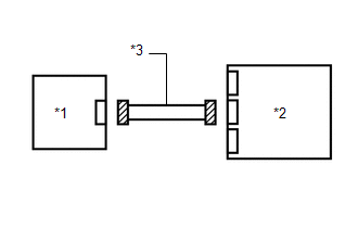
(c) Check that the connectors are properly connected to the airbag ECU assembly and front airbag sensor LH.
OK:
The connectors are properly connected.
| NG | .gif) | CONNECT CONNECTORS PROPERLY |
|
.gif)
| 2. |
CHECK CONNECTORS |
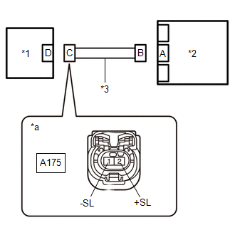
(a) Disconnect the connectors from the airbag ECU assembly and front airbag sensor LH.
| (b) Check that the terminals of the connectors are not deformed or damaged. OK: The terminals of the connectors are not deformed or damaged. |
|
| NG | | REPAIR OR REPLACE HARNESS OR CONNECTOR |
|
| 3. |
CHECK HARNESS AND CONNECTOR (SHORT) |
| (a) Measure the resistance according to the value(s) in the table below. Standard Resistance:
|
|
| NG | | REPAIR OR REPLACE HARNESS OR CONNECTOR |
|
| 4. |
CHECK HARNESS AND CONNECTOR (SHORT TO GROUND) |
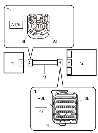
| (a) Measure the resistance according to the value(s) in the table below. Standard Resistance:
|
|
| NG | | REPAIR OR REPLACE HARNESS OR CONNECTOR |
|
| 5. |
CHECK HARNESS AND CONNECTOR (SHORT TO B+) |
(a) Connect the cable to the negative (-) battery terminal.
(b) Turn the ignition switch to ON.
| (c) Measure the voltage according to the value(s) in the table below. Standard Voltage:
Result:
|
|
(d) Turn the ignition switch off.
(e) Disconnect the cable from the negative (-) battery terminal.
CAUTION:
Wait at least 60 seconds after disconnecting the cable from the negative (-) battery terminal to disable the SRS system.
| NG | | REPAIR OR REPLACE HARNESS OR CONNECTOR |
|
| 6. |
CHECK HARNESS AND CONNECTOR (OPEN) |
(a) Using a service wire, connect terminals 30 (+SL) and 31 (-SL) of connector B.
NOTICE:
Do not forcibly insert the service wire into the terminals of the connector when connecting the wire.
| (b) Measure the resistance according to the value(s) in the table below. Standard Resistance:
Result:
|
|
(c) Disconnect the service wire from connector B.
| NG | | REPAIR OR REPLACE HARNESS OR CONNECTOR |
|
| 7. |
CLEAR DTC |
| (a) Connect the connector to the airbag ECU assembly. |
|
(b) Interchange the front airbag sensor LH with RH and connect the connectors.
(c) Connect the cable to the negative (-) battery terminal.
(d) Turn the ignition switch to ON, and wait for at least 60 seconds.
(e) Clear the DTCs stored in memory.
Body Electrical > SRS Airbag > Clear DTCs(f) Turn the ignition switch off.
|
| 8. |
CHECK FRONT AIRBAG SENSOR LH |
(a) Turn the ignition switch to ON, and wait for at least 60 seconds.
(b) Check for DTCs.
Body Electrical > SRS Airbag > Trouble Codes| Result |
Proceed to |
|---|---|
| B009083 is output |
A |
| B009583 is output |
B |
| B009083 and B009583 are not output |
C |
HINT:
Codes other than DTCs B009083 and B009583 may be output at this time, but they are not related to this check.
(c) Turn the ignition switch off.
(d) Disconnect the cable from the negative (-) battery terminal.
CAUTION:
Wait at least 60 seconds after disconnecting the cable from the negative (-) battery terminal to disable the SRS system.
(e) Return the front airbag sensor LH and RH to their original positions and connect the connectors.
| A |
| REPLACE AIRBAG ECU ASSEMBLY |
| B |
| REPLACE FRONT AIRBAG SENSOR LH |
| C |
| USE SIMULATION METHOD TO CHECK |
READ NEXT:
 Left Frontal Restraints Sensor Signal Below Allowable Range (B009084)
DESCRIPTION
DTC No. Detection Item
DTC Detection Condition Trouble Area
Warning Indicate Test Mode / Check Mode
B009084 Left Frontal Restraints Sensor Signal Below Allo
Left Frontal Restraints Sensor Signal Above Allowable Range (B009085)
DESCRIPTION
DTC No. Detection Item
DTC Detection Condition Trouble Area
Warning Indicate Test Mode / Check Mode
B009085 Left Frontal Restraints Sensor Signal Above Allo
Left Frontal Restraints Sensor Missing Message (B009087)
DESCRIPTION
DTC No. Detection Item
DTC Detection Condition Trouble Area
Warning Indicate Test Mode / Check Mode
B009087 Left Frontal Restraints Sensor Missing Message
SEE MORE:
 P-Door P/W Motor Component Internal Failure (B231E96)
DESCRIPTION The main body ECU (multiplex network body ECU) communicates with the power window regulator motor assembly (for front passenger door) via LIN communication.
This DTC is stored when a power window regulator motor assembly (for front passenger door) is malfunctioning, or the ECU built int
A/F (O2) Sensor Signal Biased/Stuck Lean Bank 1 Sensor 1 Circuit Current Above Threshold (P219519,P219524,P219618,P219623)
DESCRIPTION Refer to DTC P003012. Click here
HINT: Although the DTC titles say O2 sensor, these DTCs relate to the air fuel ratio sensor (sensor 1).
DTC No. Detection Item
DTC Detection Condition Trouble Area
MIL Note
P219519 A/F (O2) Sensor Signal Biased/Stuck Le
