Toyota Corolla Cross: Removal
REMOVAL
CAUTION / NOTICE / HINT
COMPONENTS (REMOVAL)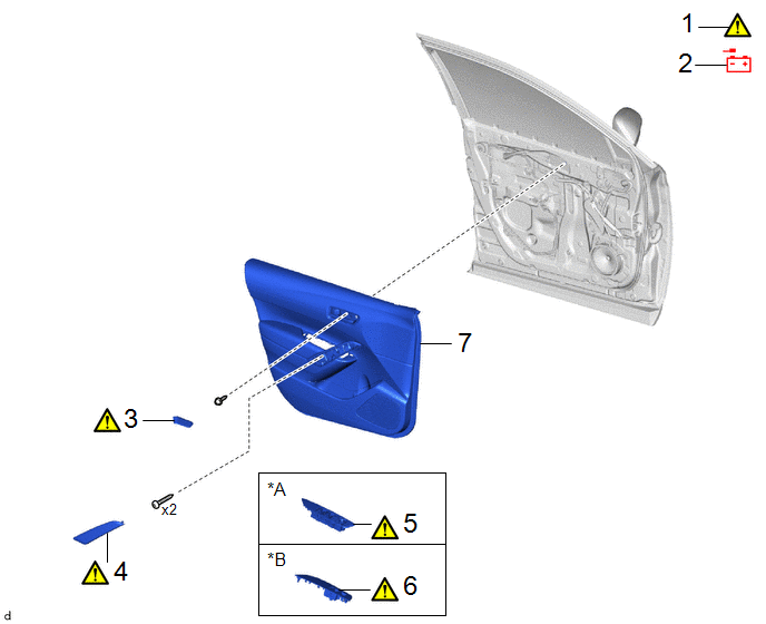
|
Procedure | Part Name Code |
.png) |
.png) |
 |
|---|---|---|---|---|---|
|
1 | PRECAUTION |
- |
|
- | - |
|
2 | DISCONNECT CABLE FROM NEGATIVE AUXILIARY BATTERY TERMINAL |
- | - |
- | - |
|
3 | FRONT DOOR INSIDE HANDLE BEZEL PLUG |
69284F |
|
- | - |
|
4 | DOOR ASSIST GRIP COVER |
74646 |
|
- | - |
|
5 | MULTIPLEX NETWORK MASTER SWITCH ASSEMBLY WITH FRONT DOOR UPPER ARMREST BASE PANEL |
- |
|
- | - |
|
6 | POWER WINDOW REGULATOR SWITCH ASSEMBLY WITH FRONT DOOR UPPER ARMREST BASE PANEL |
- |
|
- | - |
|
7 | FRONT DOOR TRIM BOARD SUB-ASSEMBLY |
67602 | - |
- | - |
|
*A | for Driver Side |
*B | for Front Passenger Side |
|
Procedure | Part Name Code |
|
|
| |
|---|---|---|---|---|---|
|
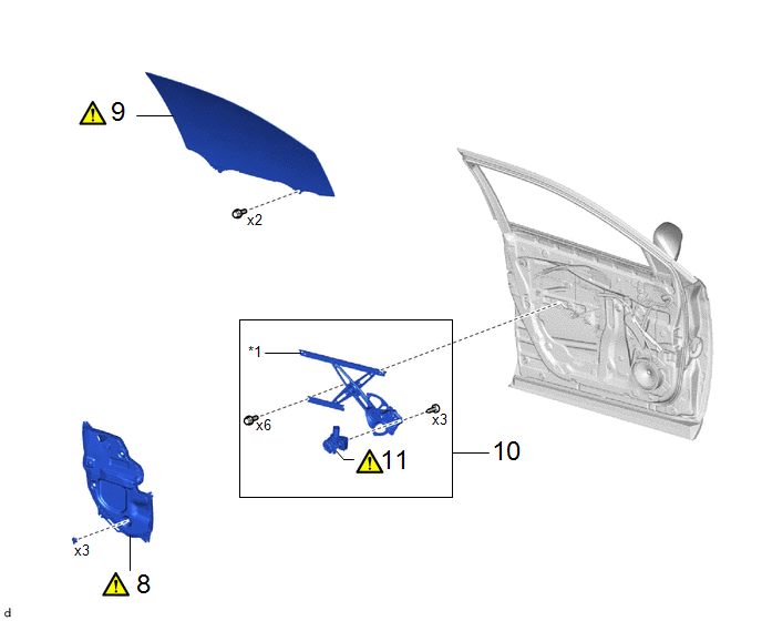
8 | FRONT DOOR SERVICE HOLE COVER |
67832 |
|
- | - |
|
9 | FRONT DOOR GLASS SUB-ASSEMBLY |
68102 |
|
- | - |
|
10 | FRONT DOOR WINDOW REGULATOR ASSEMBLY |
- | - |
- | - |
|
11 | POWER WINDOW REGULATOR MOTOR ASSEMBLY |
85720D |
|
- | - |
|
*1 | FRONT DOOR WINDOW REGULATOR SUB-ASSEMBLY |
- | - |
CAUTION / NOTICE / HINT
The necessary procedures (adjustment, calibration, initialization, or registration) that must be performed after parts are removed and installed, or replaced during power window regulator motor assembly removal/installation are shown below.
Necessary Procedures After Parts Removed/Installed/Replaced|
Replaced Part or Performed Procedure |
Necessary Procedure | Effect/Inoperative Function when Necessary Procedure not Performed |
Link |
|---|---|---|---|
| *1: Even when not replacing the part, it is necessary to perform the specified necessary procedures after installation. | |||
| Power window regulator motor assembly*1 |
Initialize power window control system |
|
|
HINT:
- When the cable is disconnected/reconnected to the auxiliary battery terminal, systems temporarily stop operating. However, each system has a function that completes learning the first time the system is used.
- Learning completes when vehicle is driven
Effect/Inoperative Function When Necessary Procedures are not Performed
Necessary Procedures
Link
*1: for Gasoline Model Front camera system
Drive the vehicle straight ahead at 15 km/h (10 mph) or more for 1 second or more.
.gif)
Stop and start system*1
Drive the vehicle until stop and start control is permitted (approximately 5 to 60 minutes)
- Learning completes when vehicle is operated normally
Effect/Inoperative Function When Necessary Procedures are not Performed
Necessary Procedures
Link
Power door lock control system
- Back door opener
Perform door unlock operation with door control switch or electrical key transmitter sub-assembly switch.
Power back door system
Fully close the back door by hand.
HINT:
Initialization is not necessary if the above procedures are performed while the back door is closed.
Air conditioning system
After the ignition switch is turned to ON, the servo motor standard position is recognized.
-
- Learning completes when vehicle is driven
- Use the same procedure for the RH side and LH side.
- The following procedure is for the LH side.
PROCEDURE
1. PRECAUTION
|
|
NOTICE: After the ignition switch is turned off, there may be a waiting time before disconnecting the negative (-) auxiliary battery terminal. Click here |
2. DISCONNECT CABLE FROM NEGATIVE AUXILIARY BATTERY TERMINAL
Click here
3. REMOVE FRONT DOOR INSIDE HANDLE BEZEL PLUG
|
|
Click here |
4. REMOVE DOOR ASSIST GRIP COVER
|
|
Click here |
5. REMOVE MULTIPLEX NETWORK MASTER SWITCH ASSEMBLY WITH FRONT DOOR UPPER ARMREST BASE PANEL (for Driver Side)
|
|
Click here |
6. REMOVE POWER WINDOW REGULATOR SWITCH ASSEMBLY WITH FRONT DOOR UPPER ARMREST BASE PANEL (for Front Passenger Side)
|
|
Click here |
7. REMOVE FRONT DOOR TRIM BOARD SUB-ASSEMBLY
Click here
8. REMOVE FRONT DOOR SERVICE HOLE COVER
|
|
Click here |
9. REMOVE FRONT DOOR GLASS SUB-ASSEMBLY
|
|
Click here |
10. REMOVE FRONT DOOR WINDOW REGULATOR ASSEMBLY
Click here
11. REMOVE POWER WINDOW REGULATOR MOTOR ASSEMBLY
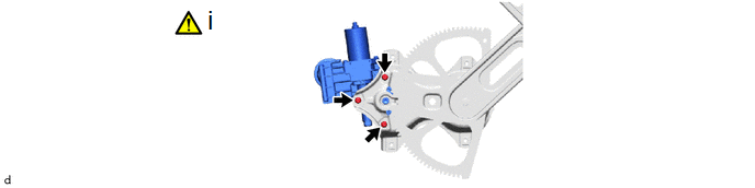
(1) Using a T25 "TORX" socket wrench, remove the 3 screws and power window regulator motor assembly.


