Toyota Corolla Cross: Inspection
INSPECTION
PROCEDURE
1. INSPECT POWER WINDOW REGULATOR MOTOR ASSEMBLY LH
(a) Check the operation.
|
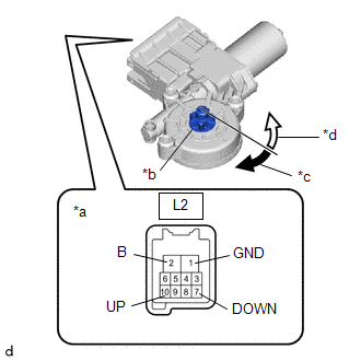
(1) Connect a positive (+) lead from the auxiliary battery to connector terminal L2-2 (B).
NOTICE: Do not connect a positive (+) lead from the auxiliary battery to any terminal other than terminal L2-2 (B) to avoid damaging the pulse sensor inside the motor. |
 |
|
*a | Component without harness connected
(Power Window Regulator Motor Assembly LH) | |
*b | Motor Gear | |
*c | Clockwise | |
*d | Counterclockwise | | |
(2) Connect a negative (-) lead from the auxiliary battery to connector terminals L2-1 (GND) and L2-7 (DOWN) or L2-10 (UP).
(3) Check that the motor gear rotates smoothly as follows:
OK:
|
Measurement Condition | Specified Condition |
- Connect a positive (+) lead from the auxiliary battery to terminal L2-2 (B), connect a negative (-) lead from the auxiliary battery to terminal L2-1 (GND), and keep them connected for 3 seconds or more.
- With terminals L2-2 (B) and L2-1 (GND) connected, connect a negative (-) lead from the auxiliary battery to terminal L2-10 (UP).
| Motor gear rotates clockwise |
- Connect a positive (+) lead from the auxiliary battery to terminal L2-2 (B), connect a negative (-) lead from the auxiliary battery to terminal L2-1 (GND), and keep them connected for 3 seconds or more.
- With terminals L2-2 (B) and L2-1 (GND) connected, connect a negative (-) lead from the auxiliary battery to terminal L2-7 (DOWN).
| Motor gear rotates counterclockwise |
- If the result is not as specified, replace the power window regulator motor assembly LH.
CAUTION:
Initialize the power window control system after installing the front door window regulator assembly.
2. INSPECT POWER WINDOW REGULATOR MOTOR ASSEMBLY RH
(a) Check the operation.
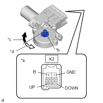
| (1) Connect a positive (+) lead from the auxiliary battery to connector terminal K2-2 (B).
NOTICE: Do not connect a positive (+) lead from the auxiliary battery to any terminal other than terminal K2-2 (B) to avoid damaging the pulse sensor inside the motor. |
 |
|
*a | Component without harness connected
(Power Window Regulator Motor Assembly RH) | |
*b | Motor Gear | |
*c | Clockwise | |
*d | Counterclockwise | | |
(2) Connect a negative (-) lead from the auxiliary battery to connector terminals K2-1 (GND) and K2-7 (DOWN) or K2-10 (UP).
(3) Check that the motor gear rotates smoothly as follows:
OK:
|
Measurement Condition | Specified Condition |
- Connect a positive (+) lead from the auxiliary battery to terminal K2-2 (B), connect a negative (-) lead from the auxiliary battery to terminal K2-1 (GND), and keep them connected for 3 seconds or more.
- With terminals K2-2 (B) and K2-1 (GND) connected, connect a negative (-) lead from the auxiliary battery to terminal K2-10 (UP).
| Motor gear rotates counterclockwise |
- Connect a positive (+) lead from the auxiliary battery to terminal K2-2 (B), connect a negative (-) lead from the auxiliary battery to terminal K2-1 (GND), and keep them connected for 3 seconds or more.
- With terminals K2-2 (B) and K2-1 (GND) connected, connect a negative (-) lead from the auxiliary battery to terminal K2-7 (DOWN).
| Motor gear rotates clockwise |
- If the result is not as specified, replace the power window regulator motor assembly RH.
CAUTION:
Initialize the power window control system after installing the front door window regulator assembly.
READ NEXT:
INSTALLATION CAUTION / NOTICE / HINT COMPONENTS (INSTALLATION)
Procedure Part Name Code
1 POWER WINDOW REGULATOR MOTOR ASSEMBLY
85720D
- -
2
REMOVAL CAUTION / NOTICE / HINT COMPONENTS (REMOVAL)
Procedure Part Name Code
1 REAR DOOR GLASS SUB-ASSEMBLY
68104
- -
2 REAR DOOR WINDOW
SEE MORE:
REMOVAL
CAUTION / NOTICE / HINT
COMPONENTS (REMOVAL)
Procedure
Part Name Code
1
IGNITION COIL ASSEMBLY
19500
-
-
2
SPARK PLUG
19100P
PARTS LOCATION ILLUSTRATION
*1 CANISTER
*2 FUEL PUMP (for Low Pressure Side)
*3 MASS AIR FLOW METER SUB-ASSEMBLY
*4 PARK / NEUTRAL POSITION SWITCH ASSEMBLY
*5 NO. 1 ENGINE ROOM RELAY BLOCK ASSEMBLY
*6 NO. 2 RELAY BLOCK ASSEMBLY
*7 FUE


