Toyota Corolla Cross: Removal
REMOVAL
CAUTION / NOTICE / HINT
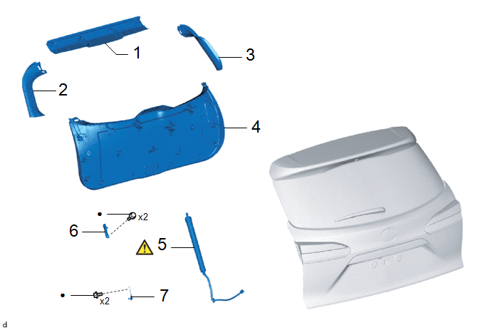
COMPONENTS (REMOVAL)
|
Procedure | Part Name Code |
.png) |
.png) |
 |
|---|---|---|---|---|---|
|
1 | BACK DOOR TRIM UPPER PANEL ASSEMBLY |
64790B | - |
- | - |
|
2 | BACK DOOR SIDE GARNISH LH |
67938A | - |
- | - |
|
3 | BACK DOOR SIDE GARNISH RH |
67937B | - |
- | - |
|
4 | BACK DOOR TRIM PANEL ASSEMBLY |
64780A | - |
- | - |
|
5 | POWER BACK DOOR UNIT ASSEMBLY SET |
68920 |
|
- | - |
|
6 | BACK DOOR DAMPER STAY UPPER BRACKET |
68946 | - |
- | - |
|
7 | BACK DOOR DAMPER STAY LOWER BRACKET |
68948 | - |
- | - |
|
● | Non-reusable part |
- | - |
CAUTION / NOTICE / HINT
HINT:
- Use the same procedure for the RH side and LH side.
- The following procedure is for the LH side.
PROCEDURE
1. REMOVE BACK DOOR TRIM UPPER PANEL ASSEMBLY
Click here .gif)
.gif)
2. REMOVE BACK DOOR SIDE GARNISH LH
Click here
.gif)
.gif)
3. REMOVE BACK DOOR SIDE GARNISH RH
(a) Use the same procedure as for the LH side.
4. REMOVE BACK DOOR TRIM PANEL ASSEMBLY
Click here .gif)
.gif)
5. REMOVE POWER BACK DOOR UNIT ASSEMBLY SET
.png) |
CAUTION:
.png) |

|
*1 | Grommet |
*2 | Stop Ring |
(1) Disconnect the connector.
(2) Disengage the grommet
(3) Using a screwdriver with its tip wrapped in protective tape, slightly raise the 2 stop rings and remove the power back door unit assembly set.
CAUTION:
Remove the power back door unit assembly set while supporting the back door by hand.
NOTICE:
Do not remove the stop rings from the power back door unit assembly set. Raise the stop rings just enough to allow the ball joints to be disengaged.
6. REMOVE BACK DOOR DAMPER STAY UPPER BRACKET

7. REMOVE BACK DOOR DAMPER STAY LOWER BRACKET
.png)


