Toyota Corolla Cross: Power Back Door Main Switch
Removal
REMOVAL
CAUTION / NOTICE / HINT
COMPONENTS (REMOVAL)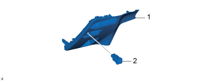
|
Procedure | Part Name Code |
.png) |
.png) |
 |
|---|---|---|---|---|---|
|
1 | LOWER NO. 1 INSTRUMENT PANEL FINISH PANEL |
55432D | - |
- | - |
|
2 | NO. 1 POWER BACK DOOR CONTROL SWITCH |
84966A | - |
- | - |
PROCEDURE
1. REMOVE LOWER NO. 1 INSTRUMENT PANEL FINISH PANEL
Click here
.gif)
2. REMOVE NO. 1 POWER BACK DOOR CONTROL SWITCH

Inspection
INSPECTION
PROCEDURE
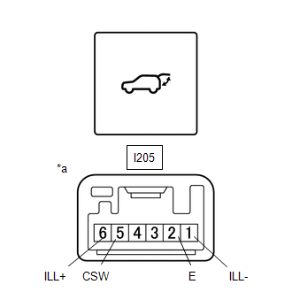
1. INSPECT NO. 1 POWER BACK DOOR CONTROL SWITCH
|
*a | Component without harness connected (No. 1 Power Back Door Control Switch) |
|
*b | Pushed |
|
*c | Not Pushed |
(a) Check the resistance of the No. 1 power back door control switch.
(1) Measure the resistance according to the value(s) in the table below.
Standard Resistance:
|
Tester Connection | Switch Condition |
Specified Condition |
|---|---|---|
| I205-5 (CSW) - I205-2 (E) |
Free | Below 1 Ω |
|
I205-5 (CSW) - I205-2 (E) |
Pushed | 10 kΩ or higher |
If the result is not as specified, replace the No. 1 power back door control switch.
(b) Check that the switch illuminates.
(1) Apply battery voltage to the No. 1 power back door control switch and check that the switch illuminates.
OK:
|
Measurement Condition | Specified Condition |
|---|---|
|
Auxiliary battery positive (+) → I205-6 (ILL+) Auxiliary battery negative (-) → I205-1 (ILL-) |
Illuminates |
If the result is not as specified, replace the No. 1 power back door control switch.
Installation
INSTALLATION
CAUTION / NOTICE / HINT
COMPONENTS (INSTALLATION)
|
Procedure | Part Name Code |
.png) |
.png) |
 |
|---|---|---|---|---|---|
|
1 | NO. 1 POWER BACK DOOR CONTROL SWITCH |
84966A | - |
- | - |
|
2 | LOWER NO. 1 INSTRUMENT PANEL FINISH PANEL |
55432D | - |
- | - |
PROCEDURE
1. INSTALL NO. 1 POWER BACK DOOR CONTROL SWITCH
2. INSTALL LOWER NO. 1 INSTRUMENT PANEL FINISH PANEL
Click here .gif)


