Toyota Corolla Cross: Installation
INSTALLATION
CAUTION / NOTICE / HINT
COMPONENTS (INSTALLATION)
|
Procedure | Part Name Code |
.png) |
.png) |
 |
|---|---|---|---|---|---|
|
1 | BACK DOOR DAMPER STAY LOWER BRACKET |
68948 |
|
- | - |
|
2 | BACK DOOR DAMPER STAY UPPER BRACKET |
68946 |
|
- | - |
|
3 | POWER BACK DOOR UNIT ASSEMBLY SET |
68920 |
|
- | - |
|
4 | BACK DOOR TRIM PANEL ASSEMBLY |
64780A | - |
- | - |
|
5 | BACK DOOR SIDE GARNISH LH |
67938A | - |
- | - |
|
6 | BACK DOOR SIDE GARNISH RH |
67937B | - |
- | - |
|
7 | BACK DOOR TRIM UPPER PANEL ASSEMBLY |
64790B | - |
- | - |
|
8 | INSPECT POWER BACK DOOR SYSTEM |
- |
|
- | - |
|
9 | INITIALIZE POWER BACK DOOR SYSTEM |
- | - |
- |
|
.png) |
N*m (kgf*cm, ft.*lbf): Specified torque |
● | Non-reusable part |
CAUTION / NOTICE / HINT
HINT:
- Use the same procedure for the RH side and LH side.
- The following procedure is for the LH side.
PROCEDURE
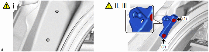
1. INSTALL BACK DOOR DAMPER STAY LOWER BRACKET
.png)
.png) |
Cleaning Area |
.png) |
Arrow Mark |
(1) Clean the bolt holes in the back door.
(2) Temporarily install the back door damper stay lower bracket with the 2 new bolts.
HINT:
With the door closed, install the back door damper stay lower bracket so that the arrow marker is facing the top side of the vehicle.
(3) Tighten the 2 bolts in the order shown in the illustration.
Torque:
9.0 N·m {92 kgf·cm, 80 in·lbf}
2. INSTALL BACK DOOR DAMPER STAY UPPER BRACKET
|
|
Cleaning Area |
|
Arrow Mark |
(1) Clean the bolt holes in the vehicle body.
(2) Temporarily install the back door damper stay upper bracket with the 2 new bolts.
HINT:
With the door closed, install the back door damper stay upper bracket so that the arrow marker is facing the top side of the vehicle.
(3) Tighten the 2 bolts in the order shown in the illustration.
Torque:
9.0 N·m {92 kgf·cm, 80 in·lbf}
3. INSTALL POWER BACK DOOR UNIT ASSEMBLY SET
|
|
CAUTION:
.png) |
4. INSTALL BACK DOOR TRIM PANEL ASSEMBLY
Click here
.gif)
5. INSTALL BACK DOOR SIDE GARNISH LH
Click here
6. INSTALL BACK DOOR SIDE GARNISH RH
HINT:
Use the same procedure as for the LH side.
7. INSTALL BACK DOOR TRIM UPPER PANEL ASSEMBLY
Click here
8. INSPECT POWER BACK DOOR SYSTEM
Click here
9. INITIALIZE POWER BACK DOOR SYSTEM
Click here

