Toyota Corolla Cross: Removal
REMOVAL
CAUTION / NOTICE / HINT
COMPONENTS (REMOVAL)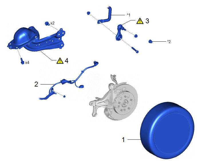
|
Procedure |
Part Name Code |
.png) |
.png) |
.png) |
|
|---|---|---|---|---|---|
|
1 |
REAR WHEEL |
- |
- |
- |
- |
|
2 |
NO. 2 PARKING BRAKE CABLE ASSEMBLY |
46430 |
- |
- |
- |
|
3 |
REAR STABILIZER LINK ASSEMBLY |
89546 |
|
- |
- |
|
4 |
REAR TRAILING ARM ASSEMBLY |
48840A |
|
- |
- |
|
*1 |
REAR STABILIZER BAR |
*2 |
CAP |
|
Procedure |
Part Name Code |
|
|
|
|
|---|---|---|---|---|---|
|
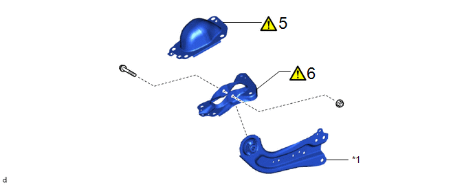
5 |
REAR NO. 1 SUSPENSION SUPPORT COVER |
48753C |
|
- |
- |
|
6 |
REAR SUSPENSION ARM BRACKET |
48727 |
|
- |
- |
|
*1 |
REAR TRAILING ARM ASSEMBLY |
- |
- |
CAUTION / NOTICE / HINT
The necessary procedures (adjustment, calibration, initialization, or registration) that must be performed after parts are removed and installed, or replaced during rear trailing arm assembly removal/installation are shown below.
Necessary Procedures After Procedure Performed|
Replaced Part or Performed Procedure |
Necessary Procedure |
Effect/Inoperative Function when Necessary Procedure not Performed |
Link |
|---|---|---|---|
|
Rear wheel alignment adjustment |
for HEV Model:
|
|
|
for Gasoline Model:
|
|
|
|
for Gasoline Model AWD:
|
Dynamic torque control AWD system |
|
|
|
Suspension, tires, etc. |
Rear television camera assembly optical axis (Back camera position setting) |
Parking Assist Monitor System |
|
|
Initialize headlight ECU subassembly LH |
Automatic headlight beam level control system |
|
HINT:
- Use the same procedure for the RH side and LH side.
- The following procedure is for the LH side.
PROCEDURE
1. REMOVE REAR WHEEL
Click here .gif)
2. SEPARATE NO. 2 PARKING BRAKE CABLE ASSEMBLY

3. REMOVE REAR STABILIZER LINK ASSEMBLY
|
|
Click here |
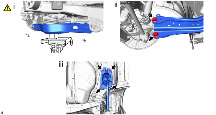
4. REMOVE REAR TRAILING ARM ASSEMBLY
|
*a |
Wooden Block |
*b |
Transmission Jack |
(1) Using a transmission jack and a wooden block, support the rear No. 2 suspension arm assembly.
NOTICE:
- When jacking up the rear No. 2 suspension arm assembly, be sure to jack it up slowly.
- Make sure to perform this operation with the vehicle kept as low as possible.
(2) Remove the 2 bolts to separate the rear trailing arm assembly from the rear axle carrier sub-assembly.
(3) Remove the 4 bolts and rear trailing arm assembly.
5. REMOVE REAR NO. 1 SUSPENSION SUPPORT COVER
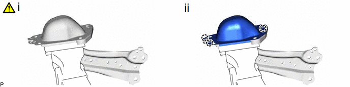
(1) Secure the rear trailing arm assembly in a vise using aluminum plates.
NOTICE:
Do not overtighten the vise.
(2) Disengage the 3 claws to remove the rear No. 1 suspension support cover.
6. REMOVE REAR SUSPENSION ARM BRACKET
|
|
NOTICE: Loosen the nut with the bolt secured. |