Toyota Corolla Cross: Rear Upper Arm
Removal
REMOVAL
CAUTION / NOTICE / HINT
COMPONENTS (REOVAL)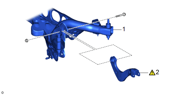
|
Procedure |
Part Name Code |
.png) |
.png) |
.png) |
|
|---|---|---|---|---|---|
|
1 |
REAR SUSPENSION MEMBER SUB-ASSEMBLY |
51206A |
- |
- |
- |
|
2 |
REAR UPPER CONTROL ARM ASSEMBLY |
48790 |
|
- |
- |
CAUTION / NOTICE / HINT
HINT:
- Use the same procedure for the RH side and LH side.
- The following procedure is for the LH side.
PROCEDURE
1. REMOVE REAR SUSPENSION MEMBER SUB-ASSEMBLY
- for Gasoline Model:
Click here
.gif)
- for HEV Model:
Click here
2. REMOVE REAR UPPER CONTROL ARM ASSEMBLY
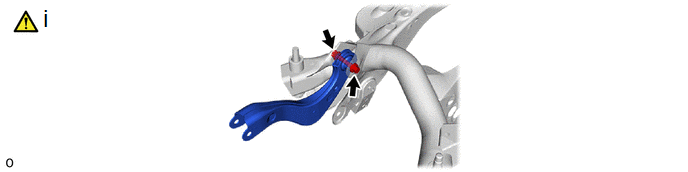
(1) Remove the bolt, nut and rear upper control arm assembly from the rear suspension member sub-assembly.
NOTICE:
Loosen the bolt with the nut secured.
Installation
INSTALLATION
CAUTION / NOTICE / HINT
COMPONENTS (INSTALLATION)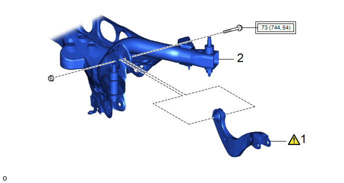
|
Procedure |
Part Name Code |
.png) |
.png) |
.png) |
|
|---|---|---|---|---|---|
|
1 |
REAR UPPER CONTROL ARM ASSEMBLY |
48790 |
|
- |
- |
|
2 |
REAR SUSPENSION MEMBER SUB-ASSEMBLY |
51206A |
- |
- |
- |
.png) |
Tightening torque for "Major areas involving basic vehicle performance such as moving/turning/stopping" : N*m (kgf*cm, ft.*lbf) |
- |
- |
CAUTION / NOTICE / HINT
HINT:
- Use the same procedure for the RH side and LH side.
- The following procedure is for the LH side.
PROCEDURE
1. INSTALL REAR UPPER CONTROL ARM ASSEMBLY
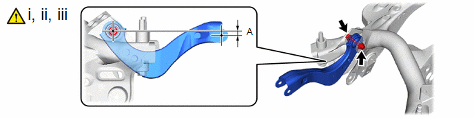
(1) Temporarily install the rear upper control arm assembly to the rear suspension member sub-assembly with the bolt and nut.
NOTICE:
- Tighten the bolt with the nut secured.
- Insert the bolt with the threaded end facing the front of the vehicle.
(2) Position the rear upper control arm assembly as shown in the illustration.
Reference Length (A):
11.5 mm (0.453 in.)
(3) Fully tighten the bolt.
Torque:
73 N·m {744 kgf·cm, 54 ft·lbf}
NOTICE:
Tighten the bolt with the nut secured.
2. INSTALL REAR SUSPENSION MEMBER SUB-ASSEMBLY
- for Gasoline Model:
Click here
.gif)
- for HEV Model:
Click here


