Toyota Corolla Cross: System Description
SYSTEM DESCRIPTION
WIRELESS CHARGER FUNCTION OUTLINE
(a) The wireless charging system enables Qi-compatible* rechargeable devices to be recharged without connecting a charging cable, by merely placing the device in the charging tray so that its charging coil is within the charging area of the mobile wireless charger cradle assembly.
HINT:
*: Qi (pronounced chee) is an international standard for wireless charging defined by the Wireless Power Consortium (WPC). The wireless charging system supports Power Class 0 of the Qi standard version 1.2.4, and supports charging rates from 5W to 10W.
(b) Qi-compatible devices which do not fit within the charging area cannot be used. If a Qi-compatible device does not operate normally, refer to the owner's manual of the device.
(c) Qi-compatible rechargeable devices can be charged.
HINT:
- "Qi" and "Qi" logo are trademarks of the Wireless Power Consortium (WPC).
- Although the wireless charging system meets Qi standards, compatibility with all Qi-compatible devices is not guaranteed.
CHARGING INDICATOR STATUS
|
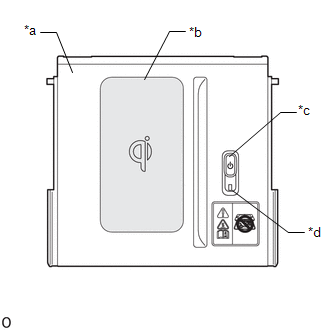
*a | Charging Tray |
|
*b | Charging Area |
|
*c | Mobile Wireless Charger Switch |
|
*d | Indicator Light (Green/Amber) |
(a) The indicator light shows the operation condition of the wireless charging system.
|
Indicator | Operation Condition | |
|---|---|---|
|
Condition | Color | |
|
Off | - |
Wireless charging system is turned off |
|
On | Green |
|
| On |
Amber |
|
| On (For 4.5 sec)*2 |
Green | Charging is stopped temporarily due to a charging suspension signal being received from the smart key system |
|
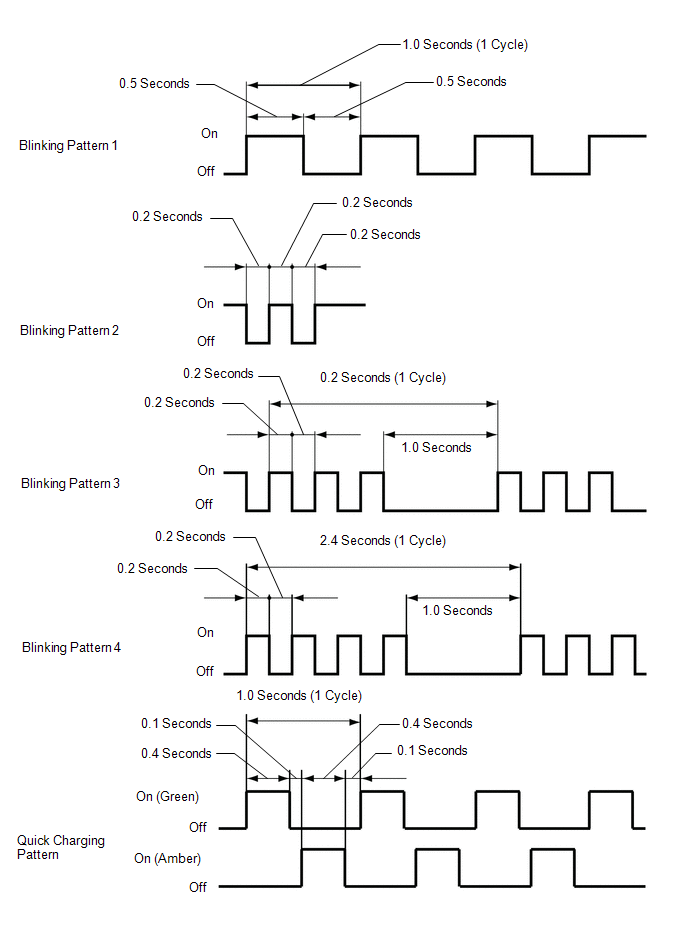
Blinks (Pattern 1)*3 |
Amber | An open in the charging suspension signal circuit is detected |
|
Blinks (Pattern 2)*3 |
Amber | The charging frequency is being changed |
|
Blinks (Pattern 3)*3 |
Amber |
|
| Blinks (Pattern 4)*3 | Amber |
The temperature of the mobile wireless charger cradle assembly is abnormally high |
|
Illuminates (Quick Charging Pattern)*3 |
Alternating Green / Amber |
A rechargeable device is being charged (quick charging in progress) |
- *1: Some mobile devices, cases or accessories may not cause the indicator (green) to illuminate when charging is complete, even though they are Qi-compatible. Check the mobile device to confirm the charge status.
- *2: If the charging suspension signal is received for less than 4.5 seconds, the indicator light (green) will remain illuminated for 4.5 seconds.
- *3: Refer to the following diagram for details about the indicator blinking patterns.
RESUMPTION OF CHARGING
(a) After charging is complete, if the rechargeable device is left in the same position on the charging area, charging will resume after 30 minutes elapse.
(b) Charging will resume if the rechargeable device is moved or repositioned within the charging area, or replaced with another rechargeable device within 30 minutes of charging being completed.
(c) If the rechargeable device is moved while it is being charged, charging will resume when the device is placed on the charging area.
HINT:
- If charging is stopped and resumed repeatedly due to the rechargeable device being moved or a communication error between the wireless charging system and rechargeable device, charging will be prohibited after a certain number of times to protect the rechargeable device.
- When a rechargeable device is moved while it is being charged via quick charging, the system considers that the device may have been replaced with a different device, and cancels quick charging.
SUSPENSION OF CHARGING DUE TO VERIFICATION OF ELECTRICAL KEY TRANSMITTER SUB-ASSEMBLY
(a) The wireless charging system uses the same radio wave frequency that is used to perform verification of the electrical key transmitter sub-assembly. Therefore, when the electrical key transmitter sub-assembly verification is being performed, the certification ECU (smart key ECU assembly) sends a charging suspension signal to the wireless charging system to suspend charging.
HINT:
- When charging is suspended due to the charging suspension signal, the indicator (green) will illuminate.
- If there is an open in the charging suspension signal circuit, the indicator (amber) will blink (pattern 1).
(b) The certification ECU (smart key ECU assembly) sends the charging suspension signal when any of the following conditions is met:
- A door is opened and closed.
- The back door opener switch is pressed.
- The back door is closed.
- The hybrid control system is started.
- An electrical key transmitter sub-assembly is not detected in the cabin.
CHARGING FREQUENCY SWITCHING FUNCTION
(a) If noise is generated in the AM radio during charging, turn the wireless charging system off and check if the noise is reduced. If the noise is reduced, press and hold the mobile wireless charging switch for approximately 2 seconds to change the charging frequency and reduce the noise.
HINT:
- When the charging frequency is being changed, the indicator (amber) blinks (pattern 2).
- For some devices, switching the charging frequency during quick charging will cause quick charging to be canceled.


