Toyota Corolla Cross: Intake System
On-vehicle Inspection
ON-VEHICLE INSPECTION
CAUTION / NOTICE / HINT
The necessary procedures (adjustment, calibration, initialization or registration) that must be performed after parts are removed and installed, or replaced when repairing air leaks in the intake system are shown below.
Necessary Procedures After Parts Removed/Installed/Replaced|
Replaced Part or Performed Procedure |
Necessary Procedure | Effect/Inoperative Function when Necessary Procedure not Performed |
Link |
|---|---|---|---|
| Air leak from intake system is repaired |
Inspection after repair |
|
|
PROCEDURE
1. INSPECT INTAKE SYSTEM
CAUTION:
To prevent injury due to contact with an operating V-ribbed belt or cooling fan, keep your hands and clothing away from the V-ribbed belt and cooling fan when working in the engine compartment with the engine running or the ignition switch ON.
.png)
HINT:
Perform "Inspection After Repair" after repairing vacuum leaks in the intake system.
Click here .gif)
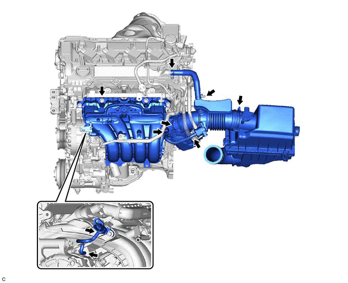
(a) Check that there are no vacuum leaks at the points shown in the illustration.
2. PERFORM INITIALIZATION
(a) Perform "Inspection After Repair" after repairing vacuum leaks in the intake system.
Click here


