Toyota Corolla Cross: Removal
REMOVAL
CAUTION / NOTICE / HINT
COMPONENTS (REMOVAL)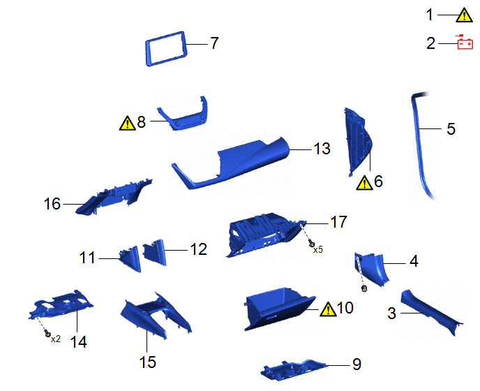
|
Procedure |
Part Name Code |
.png) |
.png) |
.png) |
|
|---|---|---|---|---|---|
|
1 |
PRECAUTION |
- |
|
- |
- |
|
2 |
DISCONNECT CABLE FROM NEGATIVE AUXILIARY BATTERY TERMINAL |
- |
- |
- |
- |
|
3 |
FRONT DOOR SCUFF PLATE RH |
67913 |
- |
- |
- |
|
4 |
COWL SIDE TRIM BOARD RH |
62111C |
- |
- |
- |
|
5 |
FRONT DOOR OPENING TRIM WEATHERSTRIP RH |
62311B |
- |
- |
- |
|
6 |
NO. 2 INSTRUMENT SIDE PANEL |
55318F |
|
- |
- |
|
7 |
CENTER INSTRUMENT CLUSTER FINISH PANEL SUB-ASSEMBLY |
55405B |
- |
- |
- |
|
8 |
AIR CONDITIONING CONTROL ASSEMBLY |
55900 |
|
- |
- |
|
9 |
NO. 2 INSTRUMENT PANEL UNDER COVER SUB-ASSEMBLY |
55607 |
- |
- |
- |
|
10 |
GLOVE COMPARTMENT DOOR ASSEMBLY |
55550 |
|
- |
- |
|
11 |
NO. 2 CONSOLE UPPER PANEL GARNISH |
58834B |
- |
- |
- |
|
12 |
NO. 1 CONSOLE UPPER PANEL GARNISH |
58833B |
- |
- |
- |
|
13 |
INSTRUMENT CLUSTER FINISH PANEL GARNISH ASSEMBLY |
55470 |
- |
- |
- |
|
14 |
NO. 1 INSTRUMENT PANEL UNDER COVER SUB-ASSEMBLY |
55606 |
- |
- |
- |
|
15 |
FRONT CONSOLE UPPER PANEL GARNISH |
58831A |
- |
- |
- |
|
16 |
LOWER CENTER INSTRUMENT PANEL FINISH PANEL |
55434F |
- |
- |
- |
|
17 |
LOWER NO. 2 INSTRUMENT PANEL FINISH PANEL |
55433B |
- |
- |
- |
|
Procedure |
Part Name Code |
|
|
|
|
|---|---|---|---|---|---|
|
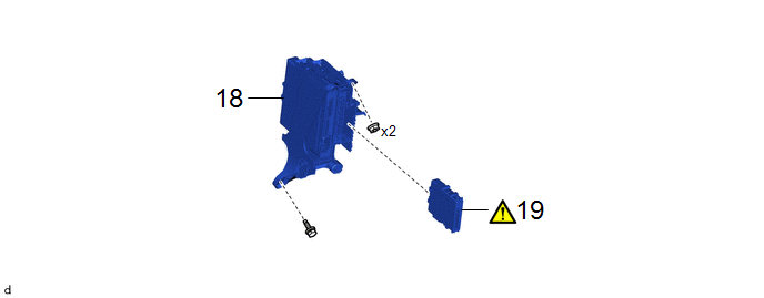
18 |
CONNECTOR HOLDER |
82666 |
- |
- |
- |
|
19 |
CENTRAL GATEWAY ECU (NETWORK GATEWAY ECU) |
89111 |
|
- |
- |
CAUTION / NOTICE / HINT
The necessary procedures (adjustment, calibration, initialization, or registration) that must be performed after parts are removed and installed, or replaced during central gateway ECU (network gateway ECU) removal/installation are shown below.
Necessary Procedures After Parts Removed/Installed/Replaced|
Replaced Part or Performed Procedure |
Necessary Procedure |
Effect/Inoperative Function when Necessary Procedure not Performed |
Link |
|---|---|---|---|
|
Central gateway ECU (network gateway ECU) |
Update ECU security key |
Vehicle Control History (RoB) are stored |
|
HINT:
When the cable is disconnected/reconnected to the auxiliary battery terminal, systems temporarily stop operating. However, each system has a function that completes learning the first time the system is used.
- Learning completes when vehicle is driven
Effect/Inoperative Function When Necessary Procedures are not Performed
Necessary Procedures
Link
*1: for Gasoline Model Front Camera System
Drive the vehicle straight ahead at 15 km/h (10 mph) or more for 1 second or more.
.gif)
Stop and start system*1
Drive the vehicle until stop and start control is permitted (approximately 5 to 60 minutes)
- Learning completes when vehicle is operated normally
Effect/Inoperative Function When Necessary Procedures are not Performed
Necessary Procedures
Link
Power door lock control system
- Back door opener
Perform door unlock operation with door control switch or electrical key transmitter sub-assembly switch.
Power back door system
Fully close the back door by hand.
HINT:
Initialization is not necessary if the above procedures are performed while the back door is closed.
Air conditioning system
After the ignition switch is turned to ON, the servo motor standard position is recognized.
-
PROCEDURE
1. PRECAUTION
|
|
NOTICE: After turning the ignition switch off, waiting time may be required before disconnecting the cable from the negative (-) auxiliary battery terminal.
|
2. DISCONNECT CABLE FROM NEGATIVE AUXILIARY BATTERY TERMINAL
- for M20A-FKS:
Click here
- for M20A-FXS:
Click here
3. REMOVE FRONT DOOR SCUFF PLATE RH
(a) Use the same procedure as for the LH side.
Click here
4. REMOVE COWL SIDE TRIM BOARD RH
(a) Use the same procedure as for the LH side.
Click here
5. DISCONNECT FRONT DOOR OPENING TRIM WEATHERSTRIP RH
(a) Use the same procedure as for the LH side.
Click here
6. REMOVE NO. 2 INSTRUMENT SIDE PANEL
|
|
|
7. REMOVE CENTER INSTRUMENT CLUSTER FINISH PANEL SUB-ASSEMBLY
Click here
8. REMOVE AIR CONDITIONING CONTROL ASSEMBLY
|
|
Click here |
9. REMOVE NO. 2 INSTRUMENT PANEL UNDER COVER SUB-ASSEMBLY
Click here
10. REMOVE GLOVE COMPARTMENT DOOR ASSEMBLY
|
|
Click here |
11. REMOVE NO. 2 CONSOLE UPPER PANEL GARNISH
Click here
12. REMOVE NO. 1 CONSOLE UPPER PANEL GARNISH
(a) Use the same procedure as for the No. 2 console upper panel garnish.
13. REMOVE INSTRUMENT CLUSTER FINISH PANEL GARNISH ASSEMBLY
Click here
14. REMOVE NO. 1 INSTRUMENT PANEL UNDER COVER SUB-ASSEMBLY
Click here
15. REMOVE FRONT CONSOLE UPPER PANEL GARNISH
Click here
16. REMOVE LOWER CENTER INSTRUMENT PANEL FINISH PANEL
Click here
17. REMOVE LOWER NO. 2 INSTRUMENT PANEL FINISH PANEL
Click here
18. REMOVE CONNECTOR HOLDER

19. REMOVE CENTRAL GATEWAY ECU (NETWORK GATEWAY ECU)
|
|
NOTICE:
|
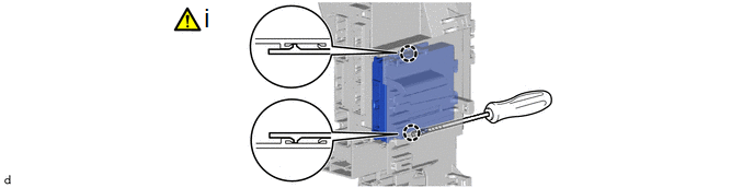
(1) Using a screwdriver with its tip wrapped in protective tape, disengage the claws to remove the central gateway ECU (network gateway ECU) as shown in the illustration.


