Toyota Corolla Cross: Installation
INSTALLATION
CAUTION / NOTICE / HINT
COMPONENTS (INSTALLATION)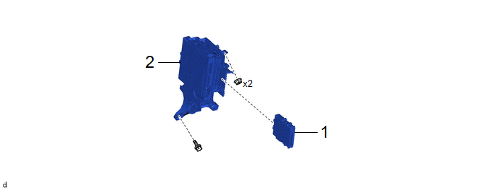
|
Procedure |
Part Name Code |
.png) |
.png) |
.png) |
|
|---|---|---|---|---|---|
|
1 |
CENTRAL GATEWAY ECU (NETWORK GATEWAY ECU) |
89111 |
- |
- |
- |
|
2 |
CONNECTOR HOLDER |
82666 |
- |
- |
- |
|
Procedure |
Part Name Code |
|
|
|
|
|---|---|---|---|---|---|
|
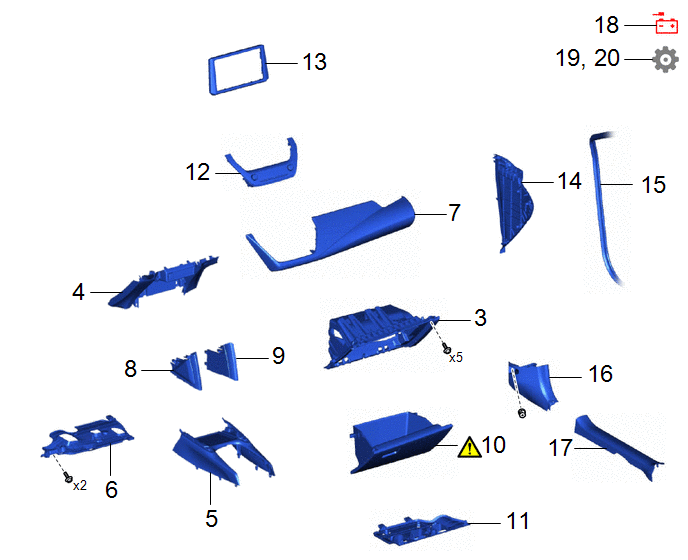
3 |
LOWER NO. 2 INSTRUMENT PANEL FINISH PANEL |
55433B |
- |
- |
- |
|
4 |
LOWER CENTER INSTRUMENT PANEL FINISH PANEL |
55434F |
- |
- |
- |
|
5 |
FRONT CONSOLE UPPER PANEL GARNISH |
58831A |
- |
- |
- |
|
6 |
NO. 1 INSTRUMENT PANEL UNDER COVER SUB-ASSEMBLY |
55606 |
- |
- |
- |
|
7 |
INSTRUMENT CLUSTER FINISH PANEL GARNISH ASSEMBLY |
55470 |
- |
- |
- |
|
8 |
NO. 2 CONSOLE UPPER PANEL GARNISH |
58834B |
- |
- |
- |
|
9 |
NO. 1 CONSOLE UPPER PANEL GARNISH |
58833B |
- |
- |
- |
|
10 |
GLOVE COMPARTMENT DOOR ASSEMBLY |
55550 |
|
- |
- |
|
11 |
NO. 2 INSTRUMENT PANEL UNDER COVER SUB-ASSEMBLY |
55607 |
- |
- |
- |
|
12 |
AIR CONDITIONING CONTROL ASSEMBLY |
55900 |
- |
- |
- |
|
13 |
CENTER INSTRUMENT CLUSTER FINISH PANEL SUB-ASSEMBLY |
55405B |
- |
- |
- |
|
14 |
NO. 2 INSTRUMENT SIDE PANEL |
55318F |
- |
- |
- |
|
15 |
FRONT DOOR OPENING TRIM WEATHERSTRIP RH |
62311B |
- |
- |
- |
|
16 |
COWL SIDE TRIM BOARD RH |
62111C |
- |
- |
- |
|
17 |
FRONT DOOR SCUFF PLATE RH |
67913 |
- |
- |
- |
|
18 |
CONNECT CABLE TO NEGATIVE AUXILIARY BATTERY TERMINAL |
- |
- |
- |
- |
|
19 |
UPDATE ECU SECURITY KEY |
- |
- |
- |
|
|
20 |
INITIALIZATION AFTER RECONNECTING AUXILIARY BATTERY TERMINAL |
- |
- |
- |
|
CAUTION / NOTICE / HINT
NOTICE:
- After replacing the central gateway ECU (network gateway ECU), make sure to perform update ECU security key.
- After performing the update ECU security key procedure, make sure to perform the initialization procedure for when the cable has been disconnected and reconnected to the negative (-) auxiliary battery terminal.
PROCEDURE
1. INSTALL CENTRAL GATEWAY ECU (NETWORK GATEWAY ECU)
2. INSTALL CONNECTOR HOLDER
3. INSTALL LOWER NO. 2 INSTRUMENT PANEL FINISH PANEL
4. INSTALL LOWER CENTER INSTRUMENT PANEL FINISH PANEL
5. INSTALL FRONT CONSOLE UPPER PANEL GARNISH
6. INSTALL NO. 1 INSTRUMENT PANEL UNDER COVER SUB-ASSEMBLY
7. INSTALL INSTRUMENT CLUSTER FINISH PANEL GARNISH ASSEMBLY
8. INSTALL NO. 2 CONSOLE UPPER PANEL GARNISH
9. INSTALL NO. 1 CONSOLE UPPER PANEL GARNISH
10. INSTALL GLOVE COMPARTMENT DOOR ASSEMBLY
|
|
Click here |
11. INSTALL NO. 2 INSTRUMENT PANEL UNDER COVER SUB-ASSEMBLY
12. INSTALL AIR CONDITIONING CONTROL ASSEMBLY
13. INSTALL CENTER INSTRUMENT CLUSTER FINISH PANEL SUB-ASSEMBLY
14. INSTALL NO. 2 INSTRUMENT SIDE PANEL
15. INSTALL FRONT DOOR OPENING TRIM WEATHERSTRIP RH
16. INSTALL COWL SIDE TRIM BOARD RH
17. INSTALL FRONT DOOR SCUFF PLATE RH
18. CONNECT CABLE TO NEGATIVE AUXILIARY BATTERY TERMINAL
- for M20A-FKS:
Click here
.gif)
- for M20A-FXS:
Click here
19. UPDATE ECU SECURITY KEY
Click here
20. INITIALIZATION AFTER RECONNECTING AUXILIARY BATTERY TERMINAL
HINT:
When disconnecting and reconnecting the auxiliary battery, there is an automatic learning function that completes learning when the respective system is used.
Click here


