Toyota Corolla Cross: Removal
REMOVAL
CAUTION / NOTICE / HINT
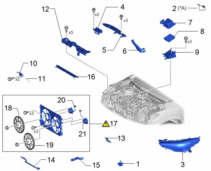
COMPONENTS (REMOVAL)
|
Procedure | Part Name Code |
.png) |
.png) |
 |
|---|---|---|---|---|---|
|
1 | INVERTER WATER PUMP WITH MOTOR ASSEMBLY |
G9040 | - |
- | - |
|
2 | DRAIN ENGINE COOLANT |
- | - |
|
- |
| 3 |
HEADLIGHT ASSEMBLY | - |
- | - |
- |
| 4 |
INLET NO. 3 AIR CLEANER |
17753 | - |
- | - |
|
5 | INLET NO. 1 AIR CLEANER |
17751 | - |
- | - |
|
6 | INLET NO. 2 AIR CLEANER |
17752 | - |
- | - |
|
7 | AIR CLEANER CAP SUB-ASSEMBLY |
17705 | - |
- | - |
|
8 | AIR CLEANER FILTER ELEMENT SUB-ASSEMBLY |
17801 | - |
- | - |
|
9 | AIR CLEANER CASE SUB-ASSEMBLY |
17701 | - |
- | - |
|
10 | HOOD LOCK WITH COURTESY LIGHT SWITCH ASSEMBLY |
53510G | - |
- | - |
|
11 | HOOD LOCK CONTROL CABLE ASSEMBLY |
53630 | - |
- | - |
|
12 | UPPER RADIATOR SUPPORT SUB-ASSEMBLY |
- | - |
- | - |
|
13 | NO. 2 WATER BY-PASS HOSE |
16264D | - |
- | - |
|
14 | INLET HYBRID RADIATOR HOSE |
G922H | - |
- | - |
|
15 | NO. 2 RADIATOR HOSE |
16572D | - |
- | - |
|
16 | NO. 2 RADIATOR AIR GUIDE |
16594A | - |
- | - |
|
17 | FAN WITH MOTOR ASSEMBLY |
- |
|
- | - |
|
18 | NO. 2 FAN |
16361B | - |
- | - |
|
19 | FAN |
16361 | - |
- | - |
|
20 | NO. 2 COOLING FAN MOTOR |
16363A | - |
- | - |
|
21 | COOLING FAN MOTOR |
16363 | - |
- | - |
|
*A | for Engine |
- | - |
PROCEDURE
1. REMOVE INVERTER WATER PUMP WITH MOTOR ASSEMBLY
Click here
.gif)
2. DRAIN ENGINE COOLANT (for Engine)
Click here .gif)
3. REMOVE HEADLIGHT ASSEMBLY
- for Bulb Type Clearance Light:
Click here
.gif)
- for LED Type Clearance Light:
Click here
.gif)
4. REMOVE INLET NO. 3 AIR CLEANER

5. REMOVE INLET NO. 1 AIR CLEANER

6. REMOVE INLET NO. 2 AIR CLEANER

7. REMOVE AIR CLEANER CAP SUB-ASSEMBLY
Click here .gif)
8. REMOVE AIR CLEANER FILTER ELEMENT SUB-ASSEMBLY
Click here .gif)
9. REMOVE AIR CLEANER CASE SUB-ASSEMBLY

10. REMOVE HOOD LOCK WITH COURTESY LIGHT SWITCH ASSEMBLY
Click here .gif)
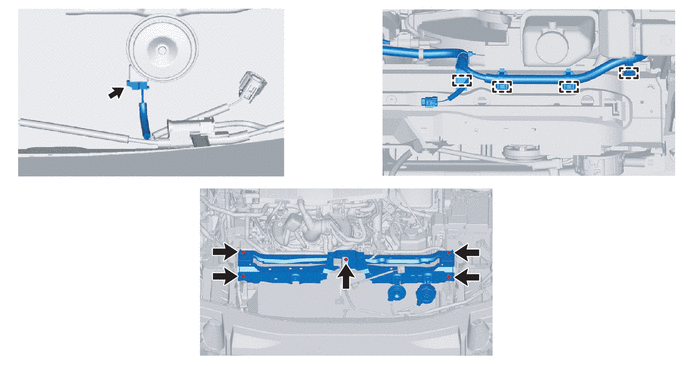
11. DISCONNECT HOOD LOCK CONTROL CABLE ASSEMBLY

12. REMOVE UPPER RADIATOR SUPPORT SUB-ASSEMBLY

13. DISCONNECT NO. 2 WATER BY-PASS HOSE

14. DISCONNECT INLET HYBRID RADIATOR HOSE

15. DISCONNECT NO. 2 RADIATOR HOSE

16. REMOVE NO. 2 RADIATOR AIR GUIDE

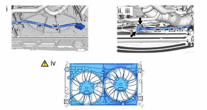
17. REMOVE FAN WITH MOTOR ASSEMBLY

(1) Disengage the 3 clamps to disconnect the wire harness from the fan shroud.
(2) Disengage the 3 clamps to disconnect the wire harness from the fan shroud.
(3) Disconnect the cooling fan motor RH connector and cooling fan motor LH connector.
(4) Disengage the 2 claws and 2 guides to remove the fan with motor assembly from the radiator assembly.
NOTICE:
Do not damage the radiator assembly when removing the fan with motor assembly.
18. REMOVE NO. 2 FAN

19. REMOVE FAN

20. REMOVE NO. 2 COOLING FAN MOTOR

21. REMOVE COOLING FAN MOTOR


