Toyota Corolla Cross: Inspection
INSPECTION
PROCEDURE
1. INSPECT PROPELLER SHAFT WITH CENTER BEARING ASSEMBLY
|
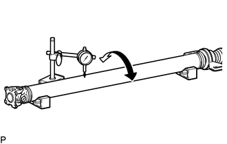
(a) Using a dial indicator, measure the runout of the intermediate shaft
assembly.
Maximum Runout:
0.6 mm (0.0236 in.)
NOTICE:
The dial indicator must be set at a right angle to the center of the
intermediate shaft assembly.
|
|
(b) If the runout is more than the maximum, replace the propeller shaft with
center bearing assembly.
|
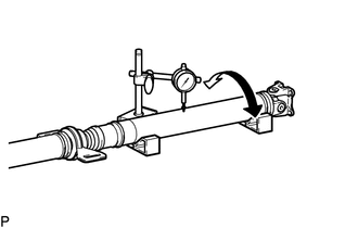
(c) Using a dial indicator, measure the runout of the propeller shaft
assembly.
Maximum Runout:
0.4 mm (0.0157 in.)
If the runout is more than the maximum, replace the propeller shaft with
center bearing assembly.
NOTICE:
The dial indicator must be set at a right angle to the center of the
propeller shaft assembly.
|
|
(d) Check that there is no excessive play and the joint part moves smoothly when
moving the joint part up and down, left and right, and in the direction of the axis.
READ NEXT:
REASSEMBLY
CAUTION / NOTICE / HINT
COMPONENTS (REASSEMBLY)
Procedure
Part Name Code
1
UNIVERSAL BOOT KIT
-
INSTALLATION
CAUTION / NOTICE / HINT
COMPONENTS (INSTALLATION)
Procedure
Part Name Code
1
TEMPORARILY INSTALL PROPELLER
Problem Symptoms Table
PROBLEM SYMPTOMS TABLE
HINT:
Use the table below to help determine the cause of problem symptoms. If multiple
suspected areas are listed, the potential causes of the symp
SEE MORE:
DTC SUMMARY MALFUNCTION DESCRIPTION These DTCs indicate that the current sensor value is abnormal. The cause of this malfunction may be one of the following: Inverter internal malfunction
Inverter with converter assembly internal circuit malfunction
Inverter low-voltage circuit malfunctio
Performing the following
operations when carrying
the electronic key on your
person starts the engine or
changes engine switch
modes.
Starting the engine
1. Check that the parking brake
is set.
2. Check that the shift lever is in
P.
3. Firmly depress the brake
pedal.
and a message will be displa