Toyota Corolla Cross: Removal
REMOVAL
CAUTION / NOTICE / HINT
COMPONENTS (REMOVAL)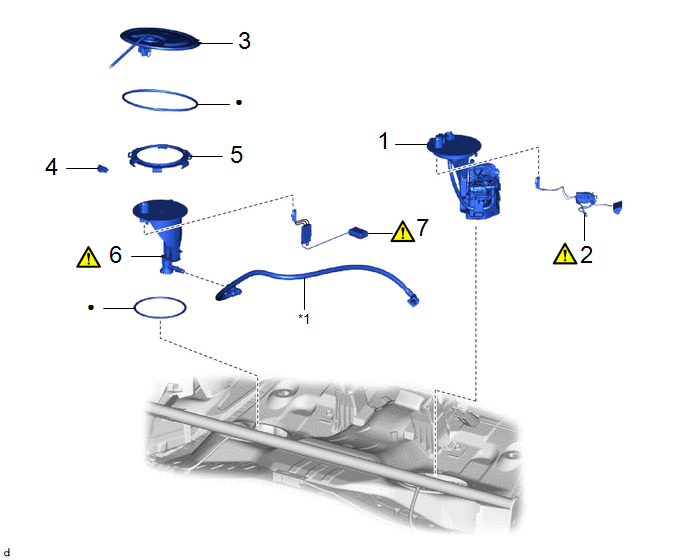
|
Procedure | Part Name Code |
.png) |
.png) |
 |
|---|---|---|---|---|---|
|
1 | FUEL SUCTION WITH PUMP AND GAUGE TUBE ASSEMBLY |
77020A | - |
- | - |
|
2 | FUEL SENDER GAUGE ASSEMBLY |
83320 |
|
- | - |
|
3 | REAR FLOOR SERVICE HOLE COVER |
58325M | - |
- | - |
|
4 | NO. 1 FUEL TUBE CLAMP |
77285D | - |
- | - |
|
5 | FUEL PUMP GAUGE RETAINER |
77144 | - |
- | - |
|
6 | FUEL TANK VENT TUBE ASSEMBLY |
77010 |
|
- | - |
|
7 | NO. 2 FUEL SENDER GAUGE ASSEMBLY |
83320B |
|
- | - |
|
*1 | FUEL RETUN VENT TUBE SUB-ASSEMBLY |
- | - |
|
● | Non-reusable part |
- | - |
CAUTION / NOTICE / HINT
CAUTION:
- Never perform work on fuel system components near any possible ignition sources.
.png)
- Vaporized fuel could ignite, resulting in a serious accident.
- Do not perform work on fuel system components without first disconnecting the cable from the negative (-) auxiliary battery terminal.
.png)
- Sparks could cause vaporized fuel to ignite, resulting in a serious accident.
NOTICE:
- After the ignition switch is turned off, the radio and display receiver assembly records various types of memory and settings. As a result, after turning the ignition switch off, make sure to wait at least 120 seconds before disconnecting the cable from the negative (-) auxiliary battery terminal.
- This procedure includes the removal of small-head bolts. Refer to Small-Head Bolts of Basic Repair Hint to identify the small-head bolts.
Click here
.gif)
HINT:
When the cable is disconnected/reconnected to the auxiliary battery terminal, systems temporarily stop operating. However, each system has a function that completes learning the first time the system is used.
- Learning completes when vehicle is driven.
Effect/Inoperative Function When Necessary Procedures are not Performed
Necessary Procedures
Link
Front camera system
Drive the vehicle straight ahead at 15 km/h (10 mph) or more for 1 second or more.
Stop and start system
Drive the vehicle until stop and start control is permitted (approximately 5 to 60 minutes)
- Learning completes when vehicle is operated normally
Effect/Inoperative Function When Necessary Procedures are not Performed
Necessary Procedures
Link
Power door lock control system
- Back door opener
Perform door unlock operation with door control switch or electrical key transmitter sub-assembly switch.
Power back door system
Fully close the back door by hand.
HINT:
Initialization is not necessary if the above procedures are performed while the back door is closed.
Air conditioning system
After the ignition switch is turned to ON, the servo motor standard position is recognized.
-
PROCEDURE
1. REMOVE FUEL SUCTION WITH PUMP AND GAUGE TUBE ASSEMBLY
Click here
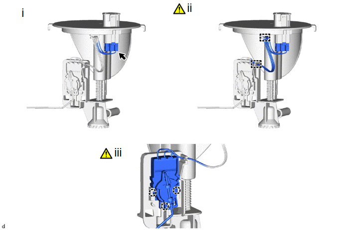
2. REMOVE FUEL SENDER GAUGE ASSEMBLY
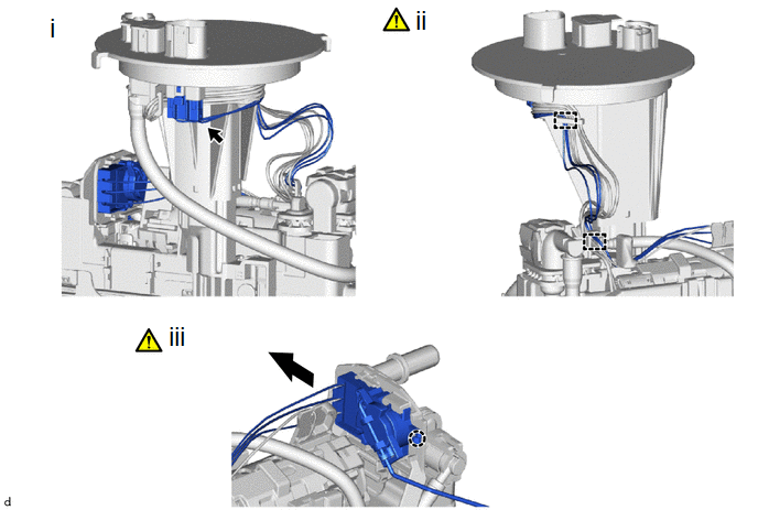
(1) Disconnect the connector from the fuel suction plate sub-assembly.
(2) Detach the 2 clamps and disconnect the wire harness.
NOTICE:
- Do not damage the wire harness.
- When disengaging each wire harness from the clamp, disengage one wire at a time.
(3) Detach the claw and remove the fuel sender gauge assembly.
NOTICE:
Be careful not to bend the arm of the fuel sender gauge assembly.
3. REMOVE REAR FLOOR SERVICE HOLE COVER (for RH Side)
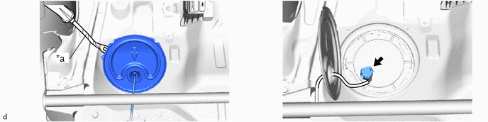
|
*a | Protective Tape |
- | - |
4. REMOVE NO.1 FUEL TUBE CLAMP
Click here
5. REMOVE FUEL PUMP GAUGE RETAINER
|
|
HINT: Perform the same procedure as for the fuel suction tube with pump and gauge assembly. Click here |
6. REMOVE FUEL TANK VENT TUBE ASSEMBLY
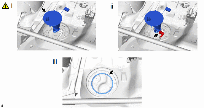
(1) Remove the fuel tank vent tube assembly from the fuel tank assembly.
NOTICE:
Be careful not to bend the arm of the fuel sender gauge assembly.
(2) Disconnect the fuel return vent tube sub-assembly.
(3) Remove the fuel suction tube set gasket from the fuel tank assembly.
7. REMOVE NO. 2 FUEL SENDER GAUGE ASSEMBLY
(1) Disconnect the connector from the fuel tank vent tube assembly.
(2) Detach the 2 clamps and disconnect the wire harness from the fuel tank vent tube assembly.
NOTICE:
Do not damage the wire harness.
(3) Detach the claw and remove the No. 2 fuel sender gauge assembly.
NOTICE:
Be careful not to bend the arm of the fuel sender gauge assembly.


