Toyota Corolla Cross: Inspection
INSPECTION
PROCEDURE
1. INSPECT FUEL SENDER GAUGE ASSEMBLY
CAUTION:
Perform the inspection in a well-ventilated area.
Do not perform the inspection near an open flame.
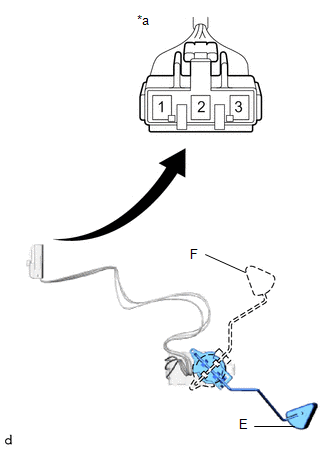
(a) Check that the float moves smoothly between F and E.
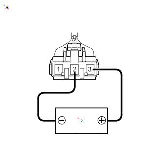
(b) Check the fuel sender gauge assembly voltage.
| (1) Apply 5 V between terminals 2 and 3.
NOTICE:
- Be careful when connecting the leads, as the fuel sender gauge assembly may be damaged if the leads are connected to the wrong terminals.
- Do not apply more than 6 V to terminals 2 or 3.
HINT: If a stable power supply is not available, connect 4 nickel-metal hydride batteries (1.2 V each) or equivalent in series. |
 |
|
*a | Component without harness connected
(Fuel Sender Gauge Assembly) | |
*b | Voltage Applied between Terminals | | |
| (2) Measure the voltage according to the value(s) in the table below.
Standard Voltage: |
Tester Connection | Float Level |
Specified Condition | |
1 - 2 | F |
4.255 to 4.605 V* | |
Between F and E | 0.345 to 4.605 V* (Gradually changes) | |
E | 0.345 to 0.695 V* |
*: The output voltage changes depending on the voltage applied to the terminals.
Output voltage (F) = (0.851 x Voltage applied to terminals) to (0.921 x Voltage applied to terminals)
Output voltage (E) = (0.069 x Voltage applied to terminals) to (0.139 x Voltage applied to terminals)
If the result is not as specified, replace the fuel sender gauge assembly. |
 |
|
*a | Component without harness connected
(Fuel Sender Gauge Assembly) | | |
2. INSPECT NO. 2 FUEL SENDER GAUGE ASSEMBLY
CAUTION:
Perform the inspection in a well-ventilated area.
Do not perform the inspection near an open flame.
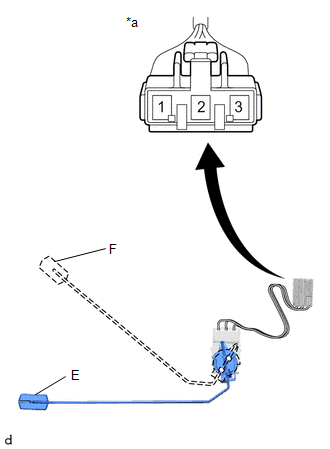
(a) Check that the float moves smoothly between F and E.
(b) Check the No. 2 fuel sender gauge assembly voltage.
| (1) Apply 5 V between terminals 2 and 3.
NOTICE:
- Be careful when connecting the leads, as the fuel sender gauge assembly may be damaged if the leads are connected to the wrong terminals.
- Do not apply more than 6 V to terminals 2 or 3.
HINT: If a stable power supply is not available, connect 4 nickel-metal hydride batteries (1.2 V each) or equivalent in series. |
|
|
|
*a | Component without harness connected
(No. 2 Fuel Sender Gauge Assembly) | |
*b | Voltage Applied between Terminals | | |
| (2) Measure the voltage according to the value(s) in the table below.
Standard Voltage: |
Tester Connection | Float Level |
Specified Condition | |
1 - 2 | F |
4.255 to 4.605 V* | |
Between F and E | 0.345 to 4.605 V* (Gradually changes) | |
E | 0.345 to 0.695 V* |
*: The output voltage changes depending on the voltage applied to the terminals.
Output voltage (F) = (0.851 x Voltage applied to terminals) to (0.921 x Voltage applied to terminals)
Output voltage (E) = (0.069 x Voltage applied to terminals) to (0.139 x Voltage applied to terminals)
If the result is not as specified, replace the No. 2 fuel sender gauge assembly. |
 |
|
*a | Component without harness connected
(No. 2 Fuel Sender Gauge Assembly) | | |
READ NEXT:
INSTALLATION CAUTION / NOTICE / HINT COMPONENTS (INSTALLATION)
Procedure Part Name Code
1 NO. 2 FUEL SENDER GAUGE ASSEMBLY
83320B
- -
PRECAUTION
CAUTION:
Never perform work on fuel system components near any possible ignition sources.
Vaporized fuel could ignite, resulting in a serious accident.
Do not perform work
SEE MORE:
DESCRIPTION The hybrid vehicle control ECU monitors the voltage of the HV battery. The hybrid vehicle control ECU stops compressor control and stores this DTC when the monitored voltage is outside the specified range.
This DTC will be stored as a history DTC. Compressor control may not resume unle
SYSTEM DIAGRAM
Communication Table
Transmitting ECU Receiving ECU
Signal Communication Method
Multiplex Network Master Switch Assembly
Power Window Regulator Motor Assembly (for Driver Door)
Power window auto up and down signal
LIN
Power Window Regulat


