Toyota Corolla Cross: Removal
REMOVAL
CAUTION / NOTICE / HINT
COMPONENTS (REMOVAL)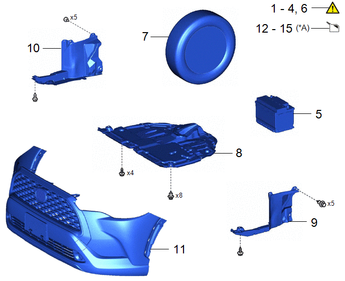
|
Procedure | Part Name Code |
.png) |
.png) |
 |
|---|---|---|---|---|---|
|
1 | PRECAUTION |
- |
|
- | - |
|
2 | RECOVER REFRIGERANT FROM REFRIGERATION SYSTEM |
- |
|
- | - |
|
3 | DISCHARGE FUEL SYSTEM PRESSURE |
- |
|
- | - |
|
4 | ALIGN FRONT WHEELS FACING STRAIGHT AHEAD |
- |
|
- | - |
|
5 | AUXILIARY BATTERY |
- | - |
- | - |
|
6 | SECURE STEERING WHEEL |
- |
|
- | - |
|
7 | FRONT WHEELS |
- | - |
- | - |
|
8 | NO. 1 ENGINE UNDER COVER ASSEMBLY |
51410 | - |
- | - |
|
9 | REAR ENGINE UNDER COVER LH |
51444A | - |
- | - |
|
10 | REAR ENGINE UNDER COVER RH |
51443C | - |
- | - |
|
11 | FRONT BUMPER ASSEMBLY |
- | - |
- | - |
|
12 | DRAIN ENGINE OIL |
- | - |
|
- |
| 13 |
DRAIN ENGINE COOLANT |
- | - |
|
- |
| 14 |
DRAIN CONTINUOUSLY VARIABLE TRANSAXLE FLUID |
- | - |
|
- |
| 15 |
DRAIN TRANSFER OIL | - |
- |
|
- |
|
*A | for AWD |
- | - |
|
Procedure | Part Name Code |
|
|
| |
|---|---|---|---|---|---|
|
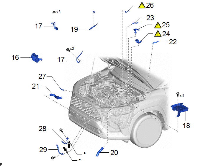
16 | ECM |
89661 | - |
- | - |
|
17 | ENGINE WIRE |
- | - |
- | - |
|
18 | BATTERY CLAMP SUB-ASSEMBLY |
74404A | - |
- | - |
|
19 | TRANSMISSION CONTROL CABLE ASSEMBLY |
33820B | - |
- | - |
|
20 | NO. 1 RADIATOR HOSE |
16571C | - |
- | - |
|
21 | NO. 2 RADIATOR HOSE |
16572D | - |
- | - |
|
22 | NO. 1 VACUUM HOSE CONNECTOR |
44777 | - |
- | - |
|
23 | NO. 1 FUEL VAPOR FEED HOSE |
23826 | - |
- | - |
|
24 | OUTLET HEATER WATER HOSE |
87246 |
|
- | - |
|
25 | INLET HEATER WATER HOSE |
87245 |
|
- | - |
|
26 | FUEL TUBE SUB-ASSEMBLY |
23901 |
|
- | - |
|
27 | NO. 2 WATER BY-PASS HOSE |
16264D | - |
- | - |
|
28 | DISCHARGE HOSE SUB-ASSEMBLY |
88703 | - |
- | - |
|
29 | SUCTION HOSE SUB-ASSEMBLY |
88704 | - |
- | - |
|
● | Non-reusable part |
- | - |
|
Procedure | Part Name Code |
|
|
| |
|---|---|---|---|---|---|
|
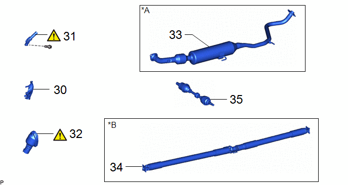
30 | COLUMN HOLE COVER SILENCER SHEET |
45259A | - |
- | - |
|
31 | NO. 2 STEERING INTERMEDIATE SHAFT ASSEMBLY |
45260 |
|
- | - |
|
32 | NO. 1 STEERING COLUMN HOLE COVER SUB-ASSEMBLY |
45025D |
|
- | - |
|
33 | FRONT EXHAUST PIPE ASSEMBLY (TWC: Rear Catalyst) |
17410 | - |
- | - |
|
34 | PROPELLER WITH CENTER BEARING SHAFT ASSEMBLY |
- | - |
- | - |
|
35 | DRIVE SHAFT ASSEMBLY |
37100 | - |
- | - |
|
*A | for 2WD |
*B | for AWD |
|
Procedure | Part Name Code |
|
|
| |
|---|---|---|---|---|---|
|
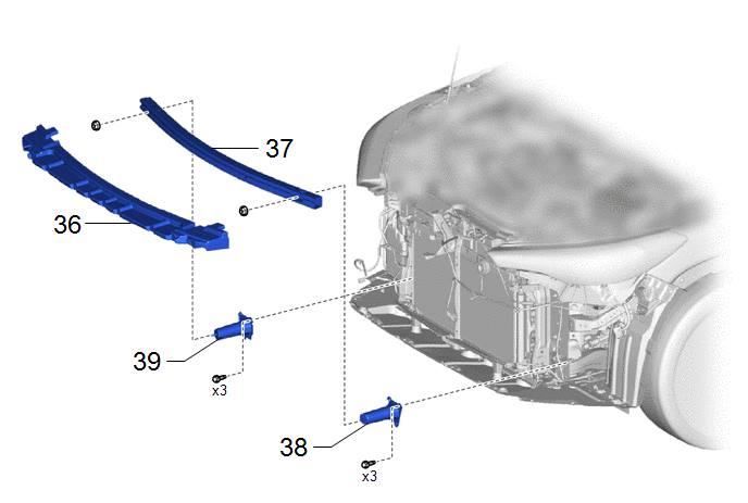
36 | FRONT BUMPER LOWER ABSORBER |
52618 | - |
- | - |
|
37 | NO. 2 FRONT BUMPER REINFORCEMENT |
52132A | - |
- | - |
|
38 | FRONT BUMPER BAR REINFORCEMENT LH |
52134C | - |
- | - |
|
39 | FRONT BUMPER BAR REINFORCEMENT RH |
52133C | - |
- | - |
|
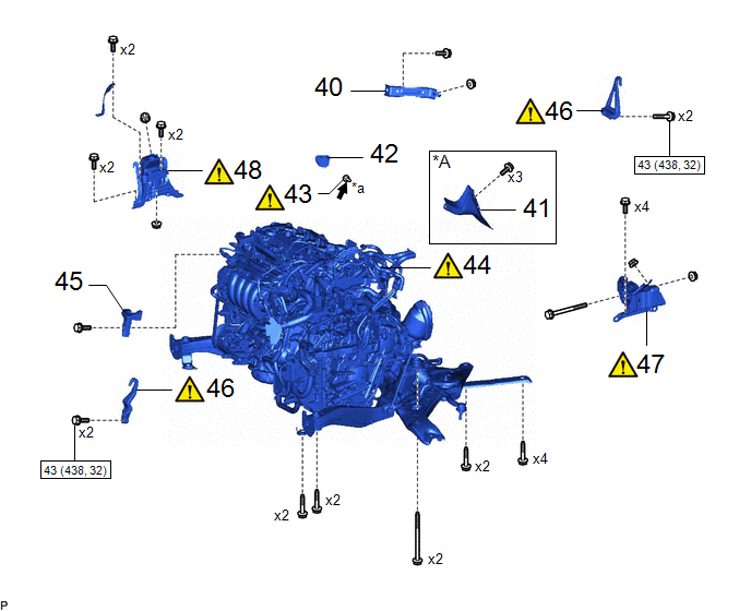
Procedure | Part Name Code |
|
|
| |
|---|---|---|---|---|---|
|
40 | MANIFOLD STAY |
17118 | - |
- | - |
|
41 | DRIVE SHAFT HEAT INSULATOR SUB-ASSEMBLY |
43409E | - |
- | - |
|
42 | FLYWHEEL HOUSING UNDER COVER |
11361J | - |
- | - |
|
43 | DRIVE PLATE AND TORQUE CONVERTER ASSEMBLY SETTING BOLT |
32101G |
|
- | - |
|
44 | ENGINE ASSEMBLY WITH TRANSAXLE |
- |
|
- | - |
|
45 | FUEL DELIVERY GUARD |
23825 | - |
- | - |
|
46 | INSTALL ENGINE HANGER |
- |
|
- | - |
|
47 | ENGINE MOUNTING INSULATOR LH |
12372A |
|
- | - |
|
48 | ENGINE MOUNTING INSULATOR SUB-ASSEMBLY RH |
12305 |
|
- | - |
|
*A | for 2WD |
- | - |
|
*a | BLACK COLOR: x 1 SILVER COLOR: x 5 | - |
- |
.png) |
N*m (kgf*cm, ft.*lbf): Specified torque |
- | - |
|
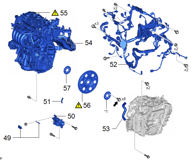
Procedure | Part Name Code |
|
|
| |
|---|---|---|---|---|---|
|
49 | ENGINE ROOM MAIN WIRE |
82111 | - |
- | - |
|
50 | STARTER ASSEMBLY |
28100 | - |
- | - |
|
51 | FLYWHEEL HOUSING SIDE COVER |
11363A | - |
- | - |
|
52 | ENGINE WIRE |
82121 | - |
- | - |
|
53 | WATER INLET HOSE |
16262 | - |
- | - |
|
54 | WATER BY-PASS HOSE ASSEMBLY |
16260 | - |
- | - |
|
55 | ENGINE ASSEMBLY |
- |
|
- | - |
|
56 | DRIVE PLATE AND RING GEAR SUB-ASSEMBLY |
32101B |
|
- | - |
|
57 | NO. 1 CRANKSHAFT POSITION SENSOR PLATE |
19315 | - |
- | - |
|
*1 | REAR DRIVE PLATE SPACER |
- | - |
|
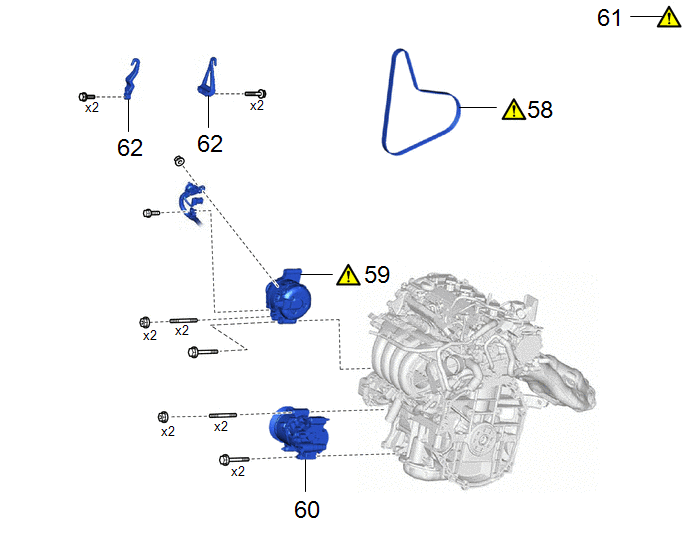
Procedure | Part Name Code |
|
|
| |
|---|---|---|---|---|---|
|
58 | V-RIBBED BELT |
16361A |
|
- | - |
|
59 | GENERATOR ASSEMBLY |
27020 |
|
- | - |
|
60 | COMPRESSOR ASSEMBLY WITH PULLEY |
88310 | - |
- | - |
|
61 | ENGINE ASSEMBLY TO ENGINE STAND |
- |
|
- | - |
|
62 | REMOVE ENGINE HANGER |
- | - |
- | - |
CAUTION / NOTICE / HINT
The necessary procedures (adjustment, calibration, initialization or registration) that must be performed after parts are removed and installed, or replaced during engine assembly removal/installation are shown below.
Necessary Procedures After Parts Removed/Installed/Replaced|
Replaced Part or Performed Procedure |
Necessary Procedure | Effect/Inoperative Function when Necessary Procedure not Performed |
Link |
|---|---|---|---|
| Battery terminal is disconnected/reconnected |
End position initial setting |
Power steering system |
|
| Inspection After Repair |
|
|
|
Continuously variable transaxle assembly |
| Deterioration of fuel efficiency |
for Initialization: for Registration: |
|
Suspension, tires, etc. |
Rear television camera assembly optical axis (Back camera position setting) |
Parking Assist Monitor System |
|
|
Front wheel alignment adjustment |
|
|
|
|
CVT fluid | ATF thermal degradation estimate reset |
The value of the Data List item "ATF Thermal Degradation Estimate" is not estimated correctly |
|
|
Bleed air from oil pump (continuously variable transaxle assembly) |
Stop and start system |
|
CAUTION:
- The engine assembly with transaxle is very heavy. Be sure to follow the procedure described in the repair manual, or the engine lifter may suddenly drop or the engine assembly with transaxle may fall off the engine lifter.
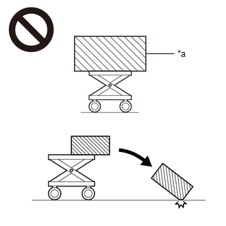
*a
An Object Exceeding Weight Limit of Engine Lifter
- To prevent burns, do not touch the engine, exhaust manifold or other high temperature components while the engine is hot.
.png)
NOTICE:
After the ignition switch is turned off, the radio and display receiver assembly records various types of memory and settings. As a result, after turning the ignition switch off, make sure to wait at least 120 seconds before disconnecting the cable from the negative (-) battery terminal.
HINT:
When the cable is disconnected/reconnected to the auxiliary battery terminal, systems temporarily stop operating. However, each system has a function that completes learning the first time the system is used.
- Learning completes when vehicle is driven.
Effect/Inoperative Function When Necessary Procedures are not Performed
Necessary Procedures
Link
Front camera system
Drive the vehicle straight ahead at 15 km/h (10 mph) or more for 1 second or more.
.gif)
Stop and start system
Drive the vehicle until stop and start control is permitted (approximately 5 to 60 minutes)
- Learning completes when vehicle is operated normally
Effect/Inoperative Function When Necessary Procedures are not Performed
Necessary Procedures
Link
Power door lock control system
- Back door opener
Perform door unlock operation with door control switch or electrical key transmitter sub-assembly switch.
Power back door system
Fully close the back door by hand.
HINT:
Initialization is not necessary if the above procedures are performed while the back door is closed.
Air conditioning system
After the ignition switch is turned to ON, the servo motor standard position is recognized.
-
PROCEDURE
1. PRECAUTION
Click here
2. RECOVER REFRIGERANT FROM REFRIGERATION SYSTEM
Click here
3. DISCHARGE FUEL SYSTEM PRESSURE
Click here
4. ALIGN FRONT WHEELS FACING STRAIGHT AHEAD
5. REMOVE AUXILIARY BATTERY
Click here
6. SECURE STEERING WHEEL
Click here
7. REMOVE FRONT WHEELS
Click here
8. REMOVE NO. 1 ENGINE UNDER COVER ASSEMBLY

9. REMOVE REAR ENGINE UNDER COVER LH
10. REMOVE REAR ENGINE UNDER COVER RH
11. REMOVE FRONT BUMPER ASSEMBLY
Click here
12. DRAIN ENGINE OIL
Click here
13. DRAIN ENGINE COOLANT
Click here
14. DRAIN CONTINUOUSLY VARIABLE TRANSAXLE FLUID
Click here
15. DRAIN TRANSFER OIL (for AWD)
16. REMOVE ECM
Click here
17. DISCONNECT ENGINE WIRE
18. REMOVE BATTERY CLAMP SUB-ASSEMBLY

19. DISCONNECT TRANSMISSION CONTROL CABLE ASSEMBLY
Click here
20. DISCONNECT NO. 1 RADIATOR HOSE

21. DISCONNECT NO. 2 RADIATOR HOSE

22. DISCONNECT NO. 1 VACUUM HOSE CONNECTOR
Click here
23. DISCONNECT NO. 1 FUEL VAPOR FEED HOSE

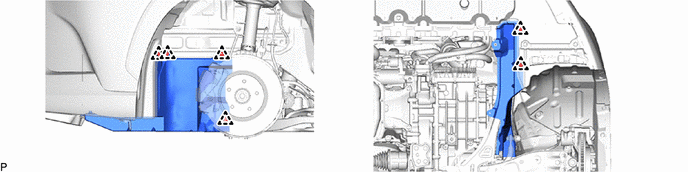
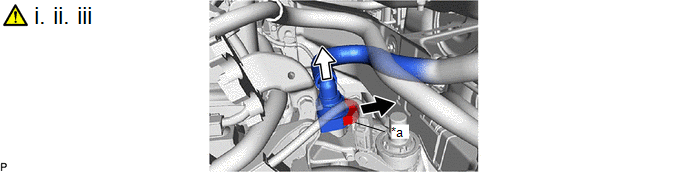
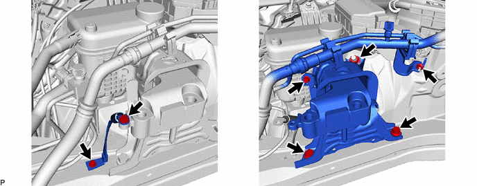
24. DISCONNECT OUTLET HEATER WATER HOSE
|
*a | Retainer |
- | - |
.png) |
Pull out |
.png) |
Pull off |
(1) Pull out the retainer to disengage the lock claws and pull off the outlet heater water hose.
(2) Check that there is no foreign matter on the sealing surfaces of the disconnected water lines. Clean them if necessary.
(3) Cover the disconnected No. 2 water by-pass pipe sub-assembly and outlet heater water hose connector with plastic bags to prevent damage and contamination.
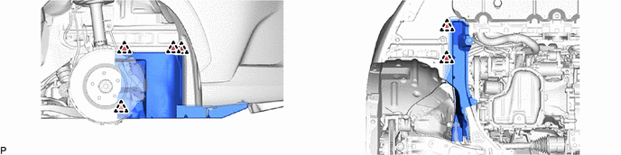
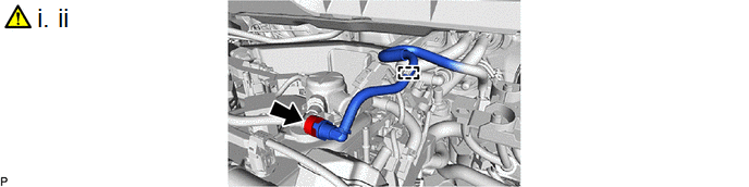
25. DISCONNECT INLET HEATER WATER HOSE
|
*a | Retainer |
- | - |
|
|
Pull out |
|
Pull off |
(1) Pull out the retainer to disengage the lock claws and pull off the inlet heater water hose.
(2) Check that there is no foreign matter on the sealing surfaces of the disconnected water lines. Clean them if necessary.
(3) Cover the disconnected flow shutting valve (water by-pass hose assembly) and inlet heater water hose connector with plastic bags to prevent damage and contamination.
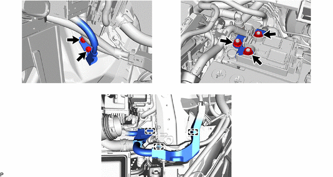
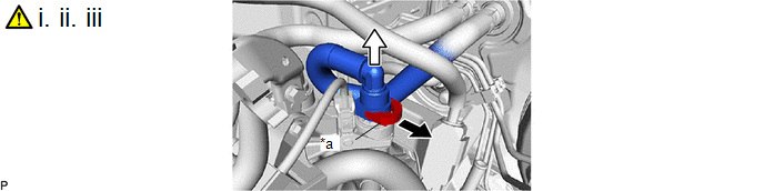
26. DISCONNECT FUEL TUBE SUB-ASSEMBLY
(1) Disengage the clamp to separate the fuel tube sub-assembly.
(2) Disconnect the fuel tube sub-assembly from the fuel pump assembly.
Click here
27. DISCONNECT NO. 2 WATER BY-PASS HOSE

28. DISCONNECT DISCHARGE HOSE SUB-ASSEMBLY
Click here
29. DISCONNECT SUCTION HOSE SUB-ASSEMBLY
Click here
30. REMOVE COLUMN HOLE COVER SILENCER SHEET
Click here
31. SEPARATE NO. 2 STEERING INTERMEDIATE SHAFT ASSEMBLY
Click here
32. SEPARATE NO. 1 STEERING COLUMN HOLE COVER SUB-ASSEMBLY
Click here
33. REMOVE FRONT EXHAUST PIPE ASSEMBLY (TWC: Rear Catalyst) (for 2WD)
Click here
34. REMOVE PROPELLER WITH CENTER BEARING SHAFT ASSEMBLY (for AWD)
Click here
35. REMOVE DRIVE SHAFT ASSEMBLY
- for 2WD:
Click here
- for AWD:
Click here
36. REMOVE FRONT BUMPER LOWER ABSORBER
Click here
37. REMOVE NO. 2 FRONT BUMPER REINFORCEMENT
Click here
38. REMOVE FRONT BUMPER BAR REINFORCEMENT LH
Click here
39. REMOVE FRONT BUMPER BAR REINFORCEMENT RH
(a) Use the same procedure as for the LH side.
40. REMOVE MANIFOLD STAY
|
|
Click here |
41. REMOVE DRIVE SHAFT HEAT INSULATOR SUB-ASSEMBLY (for 2WD)
Click here
42. REMOVE FLYWHEEL HOUSING UNDER COVER

.png) |
Remove in this Direction |
- | - |
43. REMOVE DRIVE PLATE AND TORQUE CONVERTER ASSEMBLY SETTING BOLT
Click here
44. REMOVE ENGINE ASSEMBLY WITH TRANSAXLE
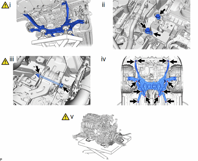
(1) Set the engine assembly with transaxle on an engine lifter.
NOTICE:
- Using height adjustment attachments and plate lift attachments, keep the engine assembly with transaxle and front suspension crossmember sub-assembly level.
- Do not perform any procedures while the engine assembly is suspended because doing so may cause the engine assembly to drop, resulting in injury. However, the engine assembly needs to be suspended when it is installed to or removed from an engine stand.
- To prevent the engine assembly from unexpectedly moving, securely support the engine assembly until it is secured to an engine stand.
- To prevent the oil pan sub-assembly from deforming, do not place any attachments under the oil pan sub-assembly of the engine assembly with transaxle.
(2) Remove the 2 bolts and nut and separate the engine mounting insulator sub-assembly RH from the engine mounting bracket RH.
(3) Remove the through bolt and nut and separate the engine mounting insulator LH from the engine mounting bracket LH.
NOTICE:
While holding the nut in place, loosen the bolt.
(4) Remove the 10 bolts to separate the front suspension crossmember sub-assembly from the vehicle.
(5) Operate the engine lifter and remove the engine assembly with transaxle from the vehicle.
NOTICE:
- Make sure that the engine assembly with transaxle is clear of all wiring and hoses.
- While lowering the engine assembly with transaxle from the vehicle, do not allow it to contact the vehicle.
45. REMOVE FUEL DELIVERY GUARD

46. INSTALL ENGINE HANGER
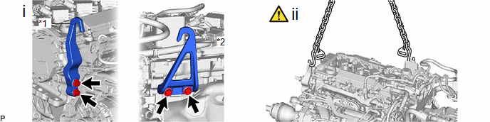
|
*1 | No. 1 Engine Hanger |
*2 | No. 2 Engine Hanger |
|
|
Bolt | - |
- |
(1) Install the No. 1 engine hanger and No. 2 engine hanger with the 4 bolts as shown in the illustration.
Torque:
43 N·m {438 kgf·cm, 32 ft·lbf}
|
No. 1 Engine Hanger | 12281-25030 |
|
No. 2 Engine Hanger | 12282-25010 |
|
Bolt | 91552-F1040 |
(2) Attach an engine sling device and hang the engine assembly with transaxle with a chain block.
NOTICE:
- Pay attention to the angle of the sling device as the engine assembly with transaxle or No. 1 engine hanger and No. 2 engine hanger may be damaged or deformed if the angle is incorrect.
- Do not perform any procedure while the engine assembly with transaxle is suspended because doing so may cause the engine assembly with transaxle to drop, resulting in injury. However, the engine assembly with transaxle needs to be suspended when it is installed to or removed from an engine stand.
47. REMOVE ENGINE MOUNTING INSULATOR LH
|
|
HINT: Perform this procedure only when replacement of the engine mounting insulator LH is necessary. |

48. REMOVE ENGINE MOUNTING INSULATOR SUB-ASSEMBLY RH
|
|
HINT: Perform this procedure only when replacement of the engine mounting insulator sub-assembly RH is necessary. |
49. DISCONNECT ENGINE ROOM MAIN WIRE
Click here
50. REMOVE STARTER ASSEMBLY
Click here
51. REMOVE FLYWHEEL HOUSING SIDE COVER

52. REMOVE ENGINE WIRE
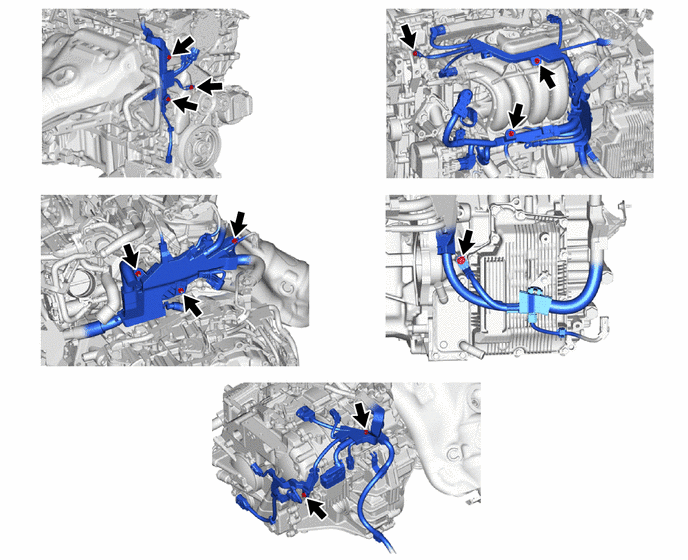
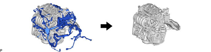
HINT:
The illustrations are representative examples, and details may differ.
53. DISCONNECT WATER INLET HOSE

54. DISCONNECT WATER BY-PASS HOSE ASSEMBLY

55. REMOVE ENGINE ASSEMBLY
Click here
56. REMOVE DRIVE PLATE AND RING GEAR SUB-ASSEMBLY
Click here
57. REMOVE NO. 1 CRANKSHAFT POSITION SENSOR PLATE
Click here
58. REMOVE V-RIBBED BELT
Click here
59. REMOVE GENERATOR ASSEMBLY
Click here
60. REMOVE COMPRESSOR ASSEMBLY WITH PULLEY
Click here
61. INSTALL ENGINE ASSEMBLY TO ENGINE STAND

62. REMOVE ENGINE HANGER


