Toyota Corolla Cross: Installation
INSTALLATION
CAUTION / NOTICE / HINT
COMPONENTS (INSTALLATION)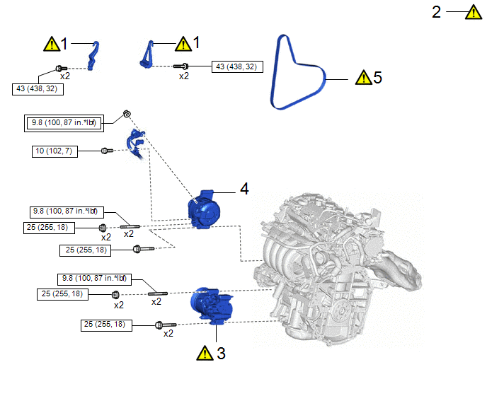
|
Procedure | Part Name Code |
.png) |
.png) |
 |
|---|---|---|---|---|---|
|
1 | INSTALL ENGINE HANGER |
- |
|
- | - |
|
2 | ENGINE ASSEMBLY FROM ENGINE STAND |
- |
|
- | - |
|
3 | COMPRESSOR ASSEMBLY WITH PULLEY |
88310 |
|
- | - |
|
4 | GENERATOR ASSEMBLY |
27020 | - |
- | - |
|
5 | V-RIBBED BELT |
16361A |
|
- | - |
.png) |
Tightening torque for "Major areas involving basic vehicle performance such as moving/turning/stopping" : N*m (kgf*cm, ft.*lbf) |
.png) |
N*m (kgf*cm, ft.*lbf): Specified torque |
|
Procedure | Part Name Code |
|
|
| |
|---|---|---|---|---|---|
|
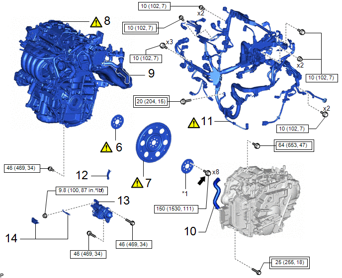
6 | NO. 1 CRANKSHAFT POSITION SENSOR PLATE |
19315 |
|
- | - |
|
7 | DRIVE PLATE AND RING GEAR SUB-ASSEMBLY |
32101B |
|
- | - |
|
8 | ENGINE ASSEMBLY |
- |
|
- | - |
|
9 | WATER BY-PASS HOSE ASSEMBLY |
16260 | - |
- | - |
|
10 | WATER INLET HOSE |
16262 | - |
- | - |
|
11 | ENGINE WIRE |
82121 |
|
- | - |
|
12 | FLYWHEEL HOUSING SIDE COVER |
11363A | - |
- | - |
|
13 | STARTER ASSEMBLY |
28100 | - |
- | - |
|
14 | ENGINE ROOM MAIN WIRE |
82111 | - |
- | - |
|
|
Tightening torque for "Major areas involving basic vehicle performance such as moving/turning/stopping" : N*m (kgf*cm, ft.*lbf) |
|
N*m (kgf*cm, ft.*lbf): Specified torque |
|
★ | Precoated part |
- | - |
.png) |
Adhesive 1324 | - |
- |
|
Procedure | Part Name Code |
|
|
| |
|---|---|---|---|---|---|
|
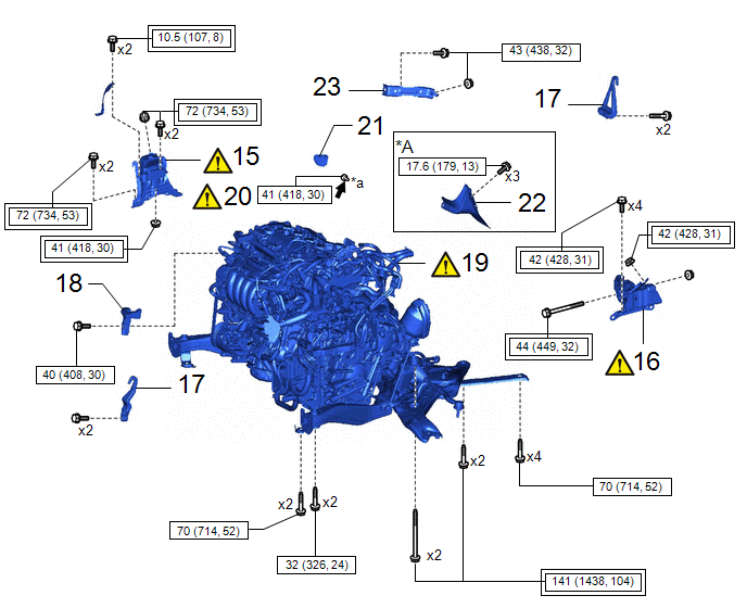
15 | ENGINE MOUNTING INSULATOR SUB-ASSEMBLY RH |
12305 |
|
- | - |
|
16 | ENGINE MOUNTING INSULATOR LH |
12372A |
|
- | - |
|
17 | REMOVE ENGINE HANGER |
- | - |
- | - |
|
18 | FUEL DELIVERY GUARD |
23825 | - |
- | - |
|
19 | ENGINE ASSEMBLY WITH TRANSAXLE |
- |
|
- | - |
|
20 | DRIVE PLATE AND TORQUE CONVERTER ASSEMBLY SETTING BOLT |
32101G |
|
- | - |
|
21 | FLYWHEEL HOUSING UNDER COVER |
12321B | - |
- | - |
|
22 | DRIVE SHAFT HEAT INSULATOR SUB-ASSEMBLY |
43409E | - |
- | - |
|
23 | MANIFOLD STAY |
11361J | - |
- | - |
|
*A | for 2WD |
- | - |
|
*a | BLACK COLOR: x 1 SILVER COLOR: x 5 | - |
- |
|
|
Tightening torque for "Major areas involving basic vehicle performance such as moving/turning/stopping" : N*m (kgf*cm, ft.*lbf) |
|
N*m (kgf*cm, ft.*lbf): Specified torque |
|
|
Adhesive 1324 | - |
- |
 FRONT BUMPER LOWER ABSORBER
|
Procedure | Part Name Code |
|
|
| |
|---|---|---|---|---|---|
|
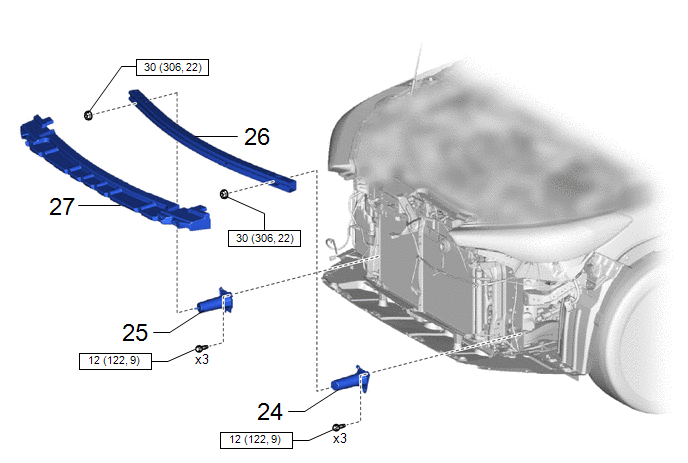
24 | FRONT BUMPER BAR REINFORCEMENT LH |
52618 | - |
- | - |
|
25 | FRONT BUMPER BAR REINFORCEMENT RH |
52132A | - |
- | - |
|
26 | NO. 2 FRONT BUMPER REINFORCEMENT |
52134C | - |
- | - |
|
27 | FRONT BUMPER LOWER ABSORBER |
52133C | - |
- | - |
|
|
N*m (kgf*cm, ft.*lbf): Specified torque |
- | - |
|
Procedure | Part Name Code |
|
|
| |
|---|---|---|---|---|---|
|
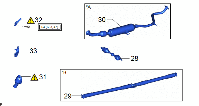
28 | DRIVE SHAFT ASSEMBLY |
- | - |
- | - |
|
29 | PROPELLER WITH CENTER BEARING SHAFT ASSEMBLY |
37100 | - |
- | - |
|
30 | FRONT EXHAUST PIPE ASSEMBLY (TWC: Rear Catalyst) |
17410 | - |
- | - |
|
31 | NO. 1 STEERING COLUMN HOLE COVER SUB-ASSEMBLY |
45025D |
|
- | - |
|
32 | NO. 2 STEERING INTERMEDIATE SHAFT ASSEMBLY |
45260 |
|
- | - |
|
33 | COLUMN HOLE COVER SILENCER SHEET |
45259A | - |
- | - |
|
*A | for 2WD |
*B | for AWD |
|
|
Tightening torque for "Major areas involving basic vehicle performance such as moving/turning/stopping" : N*m (kgf*cm, ft.*lbf) |
- | - |
|
Procedure | Part Name Code |
|
|
| |
|---|---|---|---|---|---|
|
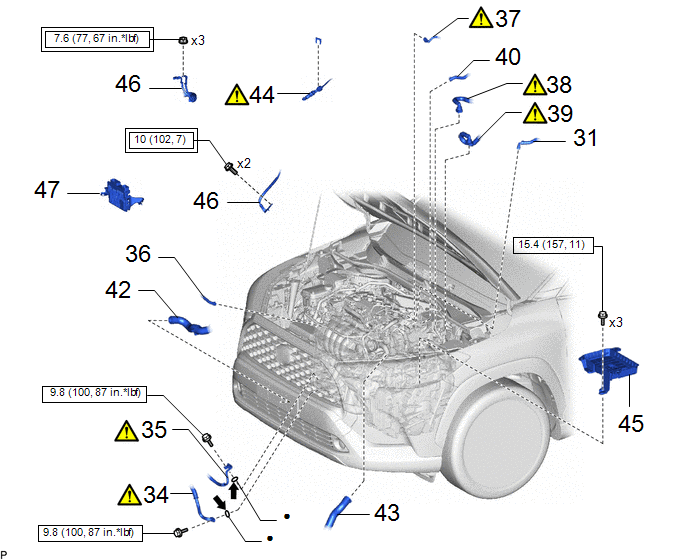
34 | SUCTION HOSE SUB-ASSEMBLY |
88704 |
|
- | - |
|
35 | DISCHARGE HOSE SUB-ASSEMBLY |
88703 |
|
- | - |
|
36 | NO. 2 WATER BY-PASS HOSE |
16264D | - |
- | - |
|
37 | FUEL TUBE SUB-ASSEMBLY |
23901 |
|
- | - |
|
38 | INLET HEATER WATER HOSE |
87245 |
|
- | - |
|
39 | OUTLET HEATER WATER HOSE |
87246 |
|
- | - |
|
40 | NO. 1 FUEL VAPOR FEED HOSE |
23829A | - |
- | - |
|
41 | NO. 1 VACUUM HOSE CONNECTOR |
44777 | - |
- | - |
|
42 | NO. 2 RADIATOR HOSE |
16572D | - |
- | - |
|
43 | NO. 1 RADIATOR HOSE |
16571C | - |
- | - |
|
44 | TRANSMISSION CONTROL CABLE ASSEMBLY |
33820B |
|
- | - |
|
45 | BATTERY CLAMP SUB-ASSEMBLY |
74404A | - |
- | - |
|
46 | ENGINE WIRE |
- | - |
- | - |
|
47 | ECM |
89661 | - |
- | - |
|
|
Tightening torque for "Major areas involving basic vehicle performance such as moving/turning/stopping" : N*m (kgf*cm, ft.*lbf) |
|
N*m (kgf*cm, ft.*lbf): Specified torque |
|
● | Non-reusable part |
- | - |
|
|
Compressor oil ND-OIL 8 or equivalent |
- | - |
|
Procedure | Part Name Code |
|
|
| |
|---|---|---|---|---|---|
|
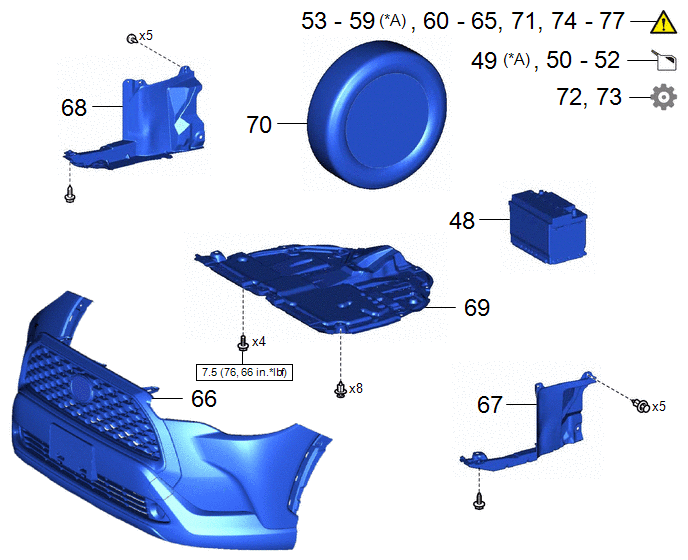
48 | BATTERY |
- | - |
- | - |
|
49 | ADD TRANSFER OIL | ||||
|
50 | ADD ENGINE OIL |
- | - |
|
- |
| 51 |
ADD ENGINE COOLANT | - |
- |
|
- |
| 52 |
ADD CONTINUOUSLY VARIABLE TRANSAXLE FLUID |
- | - |
|
- |
| 53 |
CHARGE AIR CONDITIONING SYSTEM WITH REFRIGERANT |
- | - |
|
- |
| 54 |
WARM UP ENGINE | - |
|
- | - |
|
55 | INSPECT SHIFT LEVER POSITION |
- |
|
- | - |
|
56 | ADJUST SHIFT LEVER POSITION |
- |
|
- | - |
|
57 | INSPECT FOR ENGINE OIL LEAK |
- |
|
- | - |
|
58 | INSPECT FOR COOLANT LEAK |
- |
|
- | - |
|
59 | INSPECT FOR TRANSFER OIL LEAK | ||||
|
60 | INSPECT FOR CONTINUOUSLY VARIABLE TRANSAXLE FLUID LEAK |
- |
|
- | - |
|
61 | INSPECT FOR REFRIGERANT LEAK |
- |
|
- | - |
|
62 | INSPECT FOR FUEL LEAK |
- |
|
- | - |
|
63 | INSPECT FOR EXHAUST GAS LEAK |
- |
|
- | - |
|
64 | CHECK ENGINE OIL LEVEL |
- |
|
- | - |
|
65 | INSPECT RADIATOR RESERVE TANK ENGINE COOLANT LEVEL |
- |
|
- | - |
|
66 | FRONT BUMPER ASSEMBLY | ||||
|
67 | REAR ENGINE UNDER COVER LH |
51444A | - |
- | - |
|
68 | REAR ENGINE UNDER COVER RH |
51443C | - |
- | - |
|
69 | NO. 1 ENGINE UNDER COVER ASSEMBLY |
51410 | - |
- | - |
|
70 | FRONT WHEELS |
- | - |
- | - |
|
71 | INSPECT AND ADJUST FRONT WHEEL ALIGNMENT |
- |
|
- | - |
|
72 | END POSITION INITIAL SETTING |
- | - |
- |
|
|
73 | PERFORM INITIALIZATION |
- | - |
- |
|
|
74 | INSPECT IGNITION TIMING |
- |
|
- | - |
|
75 | INSPECT ENGINE IDLE SPEED |
- |
|
- | - |
|
76 | INSPECT CO/HC |
- |
|
- | - |
|
77 | CHECK SPEED SENSOR SIGNAL |
- |
|
- | - |
|
*A | for AWD |
- | - |
|
|
N*m (kgf*cm, ft.*lbf): Specified torque |
- | - |
CAUTION / NOTICE / HINT
CAUTION:
The engine assembly with transaxle is very heavy. Be sure to follow the procedure described in the repair manual, or the engine lifter may suddenly drop.
HINT:
Perform "Inspection After Repair" after replacing the engine assembly.
Click here .gif)
PROCEDURE
1. INSTALL ENGINE HANGER
Click here
2. REMOVE ENGINE ASSEMBLY FROM ENGINE STAND
3. INSTALL COMPRESSOR ASSEMBLY WITH PULLEY
Click here
4. INSTALL GENERATOR ASSEMBLY
Click here
5. INSTALL V-RIBBED BELT
Click here
6. INSTALL NO. 1 CRANKSHAFT POSITION SENSOR PLATE
|
|
Click here |
7. INSTALL DRIVE PLATE AND RING GEAR SUB-ASSEMBLY
|
|
Click here |
8. INSTALL ENGINE ASSEMBLY
|
|
Click here |
9. CONNECT WATER BY-PASS HOSE ASSEMBLY
10. CONNECT WATER INLET HOSE
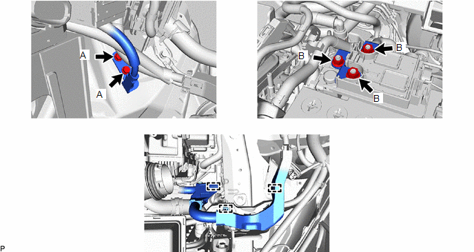
11. INSTALL ENGINE WIRE
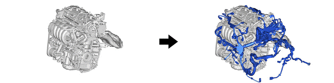
HINT:
The illustrations are representative examples, and details may differ.
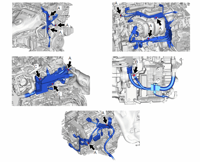
Torque:
Bolt (A), Nut (C) :
10 N·m {102 kgf·cm, 7 ft·lbf}
Bolt (B) :
20 N·m {204 kgf·cm, 15 ft·lbf}
12. INSTALL FLYWHEEL HOUSING SIDE COVER
13. INSTALL STARTER ASSEMBLY
Click here
14. INSTALL ENGINE ROOM MAIN WIRE
Click here
15. INSTALL ENGINE MOUNTING INSULATOR SUB-ASSEMBLY RH
|
|
HINT: Perform this procedure only when replacement of the engine mounting insulator sub-assembly RH is necessary. |
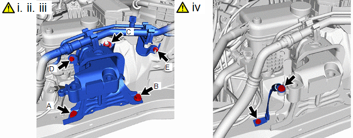
(1) Temporarily install the engine mounting insulator sub-assembly RH to the vehicle.
(2) Install the 2 bolts and nut in the order shown in the illustration.
Torque:
72 N·m {734 kgf·cm, 53 ft·lbf}
NOTICE:
Temporarily tighten the bolt (A), and then fully tighten the 2 bolts and nut in the order of (B), (A) and (C).
(3) Connect the air conditioner tube and accessory assembly with the bolt and nut.
Torque:
Bolt (D), Nut (E) :
9.8 N·m {100 kgf·cm, 87 in·lbf}
(4) Install the No. 2 earth wire to the engine mounting insulator sub-assembly RH and vehicle with the 2 bolts.
Torque:
10.5 N·m {107 kgf·cm, 8 ft·lbf}
16. INSTALL ENGINE MOUNTING INSULATOR LH
|
|
HINT: Perform this procedure only when replacement of the engine mounting insulator LH is necessary. |

(1) Temporarily install the engine mounting insulator LH to the vehicle.
(2) Install the 4 bolts and nut in the order shown in the illustration.
Torque:
42 N·m {428 kgf·cm, 31 ft·lbf}
NOTICE:
Temporarily tighten the bolt (A), and then fully tighten the 4 bolts and nut in the order of (B), (C), (D), (A) and (E).
17. REMOVE ENGINE HANGER
18. INSTALL FUEL DELIVERY GUARD
Torque:
40 N·m {408 kgf·cm, 30 ft·lbf}
19. INSTALL ENGINE ASSEMBLY WITH TRANSAXLE
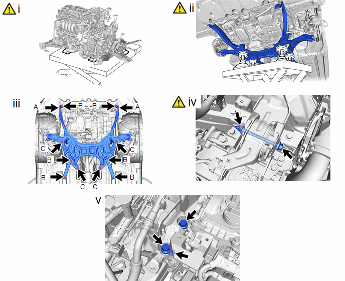
(1) Using height adjustment attachments and plate lift attachments to keep the engine assembly with transaxle and front suspension crossmember sub-assembly level, set an engine lifter underneath the engine assembly with transaxle and front suspension crossmember sub-assembly.
NOTICE:
- Using height adjustment attachments and plate lift attachments, keep the engine assembly with transaxle horizontal.
- Do not perform any procedures while the engine assembly is suspended because doing so may cause the engine assembly to drop, resulting in injury. However, the engine assembly needs to be suspended when it is installed to or removed from an engine stand.
- To prevent the oil pan sub-assembly from deforming, do not place any attachments under the oil pan sub-assembly of the engine assembly with transaxle.
(2) Operate the engine lifter and install the engine assembly with transaxle to the vehicle.
CAUTION:
Do not raise the engine assembly with transaxle more than necessary. If the engine assembly with transaxle is raised excessively, the vehicle may also be lifted up.
NOTICE:
- Make sure that the engine assembly with transaxle is clear of all wiring and hoses.
- While raising the engine assembly with transaxle into the vehicle, do not allow it to contact the vehicle.
(3) Connect the front suspension crossmember sub-assembly to the vehicle with the 12 bolts.
Torque:
Bolt (A) :
32 N·m {326 kgf·cm, 24 ft·lbf}
Bolt (B) :
70 N·m {714 kgf·cm, 52 ft·lbf}
Bolt (C) :
141 N·m {1438 kgf·cm, 104 ft·lbf}
(4) Install the engine mounting insulator LH to the engine mounting bracket LH with the through bolt and nut in the order shown in the illustration.
Torque:
44 N·m {449 kgf·cm, 32 ft·lbf}
NOTICE:
While holding the nut in place, tighten the through bolt.
(5) Install the engine mounting insulator sub-assembly RH to the engine mounting bracket RH with the 2 bolts and nut.
Torque:
Bolt :
72 N·m {734 kgf·cm, 53 ft·lbf}
Nut :
41 N·m {418 kgf·cm, 30 ft·lbf}
20. INSTALL DRIVE PLATE AND TORQUE CONVERTER ASSEMBLY SETTING BOLT
Click here
21. INSTALL FLYWHEEL HOUSING UNDER COVER
22. INSTALL DRIVE SHAFT HEAT INSULATOR SUB-ASSEMBLY (for 2WD)
Click here
23. INSTALL MANIFOLD STAY
Click here
24. INSTALL FRONT BUMPER BAR REINFORCEMENT LH
25. INSTALL FRONT BUMPER BAR REINFORCEMENT RH
26. INSTALL NO. 2 FRONT BUMPER REINFORCEMENT
27. INSTALL FRONT BUMPER LOWER ABSORBER
28. INSTALL DRIVE SHAFT ASSEMBLY
- for 2WD
Click here
- for AWD
Click here
29. INSTALL PROPELLER WITH CENTER BEARING SHAFT ASSEMBLY (for AWD)
30. INSTALL FRONT EXHAUST PIPE ASSEMBLY (TWC: Rear Catalyst) (for 2WD)
Click here
31. CONNECT NO. 1 STEERING COLUMN HOLE COVER SUB-ASSEMBLY
|
|
Click here |
32. CONNECT NO. 2 STEERING INTERMEDIATE SHAFT ASSEMBLY
|
|
Click here |
33. INSTALL COLUMN HOLE COVER SILENCER SHEET
Click here
34. CONNECT SUCTION HOSE SUB-ASSEMBLY
Click here
35. CONNECT DISCHARGE HOSE SUB-ASSEMBLY
Click here
36. CONNECT NO. 2 WATER BY-PASS HOSE
37. CONNECT FUEL TUBE SUB-ASSEMBLY
.png)
(1) Connect the fuel tube sub-assembly to the fuel pump assembly.
Click here
(2) Engage the clamp to connect the fuel tube sub-assembly.
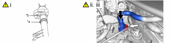
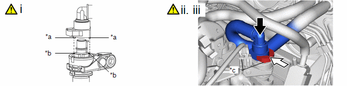
38. CONNECT INLET HEATER WATER HOSE
|
*a | Protrusion |
*b | Cutout |
|
*c | Retainer |
- | - |
|
|
Push |
.png) |
Push in |
(1) Align the protrusions of the inlet heater water hose connector with the cutouts in the flow shutting valve (water by-pass hose assembly) and push them together until the inlet heater water hose connector makes a "click" sound.
(2) Push in the retainer.
(3) Check that the flow shutting valve (water by-pass hose assembly) and inlet heater water hose connector are securely connected by pulling on them.
39. CONNECT OUTLET HEATER WATER HOSE
|
*a | Protrusion |
*b | Cutout |
|
*c | Retainer |
- | - |
|
|
Push |
|
Push in |
(1) Align the protrusion of the No. 2 water by-pass pipe sub-assembly with the cutout in the outlet heater water hose connector and push them together until the outlet heater water hose connector makes a "click" sound.
(2) Push in the retainer.
(3) Check that the No. 2 water by-pass pipe sub-assembly and outlet heater water hose connector are securely connected by pulling on them.
40. CONNECT NO. 1 FUEL VAPOR FEED HOSE
41. CONNECT NO. 1 VACUUM HOSE CONNECTOR
Click here
42. CONNECT NO. 2 RADIATOR HOSE
43. CONNECT NO. 1 RADIATOR HOSE
44. CONNECT TRANSMISSION CONTROL CABLE ASSEMBLY
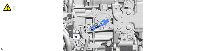
|
*a | N |
- | - |
(1) Turn the transmission control shaft lever clockwise until it stops, then turn it counterclockwise 2 notches.
NOTICE:
If the transmission control shaft lever is turned counterclockwise more than necessary, manual valve link lever sub-assembly may separate from the manual valve.
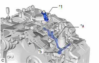
|
*1 | Transmission Control Shaft Lever |
|
*a | Manual Valve Link Lever Sub-assembly |
|
*b | Manual Valve |
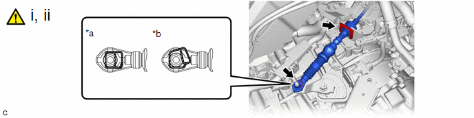
|
*a | Correct |
*b | Incorrect |
(1) Connect the transmission control cable assembly to the No. 1 transmission control cable bracket with a new clip.
(2) Connect the transmission control cable assembly to the transmission control shaft lever as shown in the illustration.
45. INSTALL BATTERY CLAMP SUB-ASSEMBLY
Torque:
15.4 N·m {157 kgf·cm, 11 ft·lbf}
46. CONNECT ENGINE WIRE
Torque:
Bolt (A) :
10 N·m {102 kgf·cm, 7 ft·lbf}
Nut (B) :
7.6 N·m {77 kgf·cm, 67 in·lbf}
47. INSTALL ECM
Click here
48. INSTALL BATTERY
Click here
49. ADD TRANSFER OIL (for AWD)
Click here
50. ADD ENGINE OIL
Click here
51. ADD ENGINE COOLANT
Click here
52. ADD CONTINUOUSLY VARIABLE TRANSAXLE FLUID
Click here
53. CHARGE AIR CONDITIONING SYSTEM WITH REFRIGERANT
Click here
54. WARM UP ENGINE
Click here
55. INSPECT SHIFT LEVER POSITION
Click here
56. ADJUST SHIFT LEVER POSITION
Click here
57. INSPECT FOR ENGINE OIL LEAK
Click here
58. INSPECT FOR COOLANT LEAK
Click here
59. INSPECT FOR TRANSFER OIL LEAK (for AWD)
Click here
60. INSPECT FOR CONTINUOUSLY VARIABLE TRANSAXLE FLUID LEAK
61. INSPECT FOR REFRIGERANT LEAK
Click here
62. INSPECT FOR FUEL LEAK
Click here
63. INSPECT FOR EXHAUST GAS LEAK
Click here
64. CHECK ENGINE OIL LEVEL
Click here
65. INSPECT RADIATOR RESERVE TANK ENGINE COOLANT LEVEL
Click here
66. INSTALL FRONT BUMPER ASSEMBLY
Click here
67. INSTALL REAR ENGINE UNDER COVER LH
68. INSTALL REAR ENGINE UNDER COVER RH
69. INSTALL NO. 1 ENGINE UNDER COVER ASSEMBLY
Torque:
7.5 N·m {76 kgf·cm, 66 in·lbf}
70. INSTALL FRONT WHEELS
Click here
71. INSPECT AND ADJUST FRONT WHEEL ALIGNMENT
Click here
72. PERFORM END POSITION INITIAL SETTING
Click here
73. PERFORM INITIALIZATION
Click here
74. INSPECT IGNITION TIMING
Click here
75. INSPECT ENGINE IDLE SPEED
Click here
76. INSPECT CO/HC
Click here
77. CHECK SPEED SENSOR SIGNAL
Click here


