Toyota Corolla Cross: Removal
REMOVAL
CAUTION / NOTICE / HINT
COMPONENTS (REMOVAL)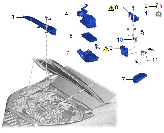
|
Procedure | Part Name Code |
.png) |
.png) |
 |
|---|---|---|---|---|---|
|
1 | PRECAUTION |
- | - |
- |
|
|
2 | CABLE FROM NEGATIVE AUXILIARY BATTERY TERMINAL |
- | - |
- | - |
|
3 | INLET NO. 1 AIR CLEANER |
17751 | - |
- | - |
|
4 | AIR CLEANER CAP WITH AIR CLEANER HOSE |
- | - |
- | - |
|
5 | AIR CLEANER FILTER ELEMENT SUB-ASSEMBLY |
17801 | - |
- | - |
|
6 | AIR CLEANER CASE SUB-ASSEMBLY |
17701 | - |
- | - |
|
7 | NO. 1 RELAY BLOCK COVER |
82662A | - |
- | - |
|
8 | ENGINE WIRE |
82121 |
|
- | - |
|
9 | ECM |
89661 |
|
- | - |
|
10 | NO. 2 ECM BRACKET |
89668 | - |
- | - |
|
11 | NO. 1 ECM BRACKET |
89667E | - |
- | - |
CAUTION / NOTICE / HINT
The necessary procedures (adjustment, calibration, initialization or registration) that must be performed after parts are removed and installed, or replaced during ECM removal/installation are shown below.
Necessary Procedures After Parts Removed/Installed/Replaced|
Replaced Part or Performed Procedure |
Necessary Procedure | Effect/Inoperative Function when Necessary Procedure not Performed |
Link |
|---|---|---|---|
| *1: When the ECM is replaced with a new one, reset memory is unnecessary. | |||
| Replacement of ECM |
Perform Vehicle Identification Number (VIN) or frame number registration |
DTC P063051 is output |
|
|
If possible, read the transaxle compensation code from the previous ECM:
|
| for K120: for K120F:
| |
|
If impossible, read the transaxle compensation code from the previous ECM:
| |||
| ECU security key |
Vehicle control history (RoB) are stored |
| |
NOTICE:
- After the ignition switch is turned off, the radio and display receiver assembly records various types of memory and settings. As a result, after turning the ignition switch off, make sure to wait at least 120 seconds before disconnecting the cable from the negative (-) auxiliary battery terminal.
- If the ECM has been struck or dropped, replace it.
- Perform Vehicle Identification Number (VIN) or frame number registration when replacing the ECM.
Click here
.gif)
HINT:
When the cable is disconnected/reconnected to the auxiliary battery terminal, systems temporarily stop operating. However, each system has a function that completes learning the first time the system is used.
- Learning completes when vehicle is driven.
Effect/Inoperative Function When Necessary Procedures are not Performed
Necessary Procedures
Link
Front camera system
Drive the vehicle straight ahead at 15 km/h (10 mph) or more for 1 second or more.
Stop and start system
Drive the vehicle until stop and start control is permitted (approximately 5 to 60 minutes)
- Learning completes when vehicle is operated normally
Effect/Inoperative Function When Necessary Procedures are not Performed
Necessary Procedures
Link
Power door lock control system
- Back door opener
Perform door unlock operation with door control switch or electrical key transmitter sub-assembly switch.
Power back door system
Fully close the back door by hand.
HINT:
Initialization is not necessary if the above procedures are performed while the back door is closed.
Air conditioning system
After the ignition switch is turned to ON, the servo motor standard position is recognized.
-
PROCEDURE
1. PRECAUTION
NOTICE:
After turning the ignition switch off, waiting time may be required before disconnecting the cable from the negative (-) auxiliary battery terminal. Therefore, make sure to read the disconnecting the cable from the negative (-) auxiliary battery terminal notices before proceeding with work.
2. DISCONNECT CABLE FROM NEGATIVE AUXILIARY BATTERY TERMINAL
Click here
3. REMOVE INLET NO. 1 AIR CLEANER
Click here
4. REMOVE AIR CLEANER CAP WITH AIR CLEANER HOSE
Click here
5. REMOVE AIR CLEANER FILTER ELEMENT SUB-ASSEMBLY
Click here
6. REMOVE AIR CLEANER CASE SUB-ASSEMBLY

7. REMOVE NO. 1 RELAY BLOCK COVER

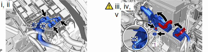
8. REMOVE ENGINE WIRE
|
*1 | Grommet |
- | - |
(1) Disconnect the 3 connectors from the No. 1 engine room relay block and No. 1 junction block assembly.
(2) Disengage the 2 claws to separate the engine wire from the No. 1 engine room relay block and No. 1 junction block assembly.
(3) Raise the 2 lock levers while pushing the locks on the levers, and disconnect the 2 ECM connectors.
NOTICE:
After disconnecting the ECM connectors, make sure that dirt, water or other foreign matter does not contact the connecting parts of the ECM connectors.
(4) Remove the bolt to separate the engine wire.
(5) Remove the grommet.
9. REMOVE ECM
|
|
NOTICE: If the ECM has been struck or dropped, replace it. |

10. REMOVE NO. 2 ECM BRACKET

11. REMOVE NO. 1 ECM BRACKET