Toyota Corolla Cross: Removal
REMOVAL
CAUTION / NOTICE / HINT
COMPONENTS (REMOVAL)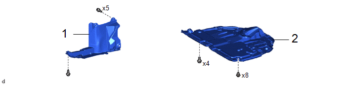
|
Procedure | Part Name Code |
.png) |
.png) |
 |
|---|---|---|---|---|---|
|
1 | NO. 1 ENGINE UNDER COVER ASSEMBLY |
51410 | - |
- | - |
|
2 | REAR ENGINE UNDER COVER RH |
51443C | - |
- | - |
|
Procedure | Part Name Code |
|
|
| |
|---|---|---|---|---|---|
|
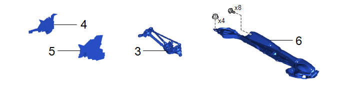
3 | WINDSHIELD WIPER MOTOR AND LINK ASSEMBLY |
- | - |
- | - |
|
4 | WATER GUARD PLATE |
55734D | - |
- | - |
|
5 | NO. 1 HEATER AIR DUCT SPLASH SHIELD SEAL |
55737B | - |
- | - |
|
6 | OUTER COWL TOP PANEL SUB-ASSEMBLY |
55701J | - |
- | - |
|
Procedure | Part Name Code |
|
|
| |
|---|---|---|---|---|---|
|
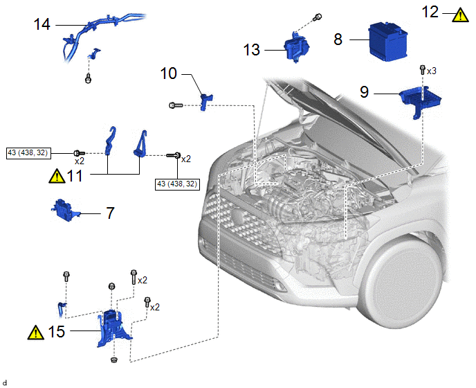
7 | ECM |
89661 | - |
- | - |
|
8 | AUXILIARY BATTERY |
- | - |
- | - |
|
9 | AUXILIARY BATTERY CLAMP SUB-ASSEMBLY |
74404A | - |
- | - |
|
10 | FUEL DELIVERY GUARD |
23825 | - |
- | - |
|
11 | ENGINE HANGER |
- |
|
- | - |
|
12 | ENGINE SUPPORT BRIDGE |
- |
|
- | - |
|
13 | RADIATOR RESERVE TANK ASSEMBLY |
16470 | - |
- | - |
|
14 | NO. 1 COOLER REFRIGERANT HOSE |
- | - |
- | - |
|
15 | ENGINE MOUNTING INSULATOR SUB-ASSEMBLY RH |
12305 |
|
- | - |
.png) |
N*m (kgf*cm, ft.*lbf): Specified torque |
- | - |
|
Procedure | Part Name Code |
|
|
| |
|---|---|---|---|---|---|
|
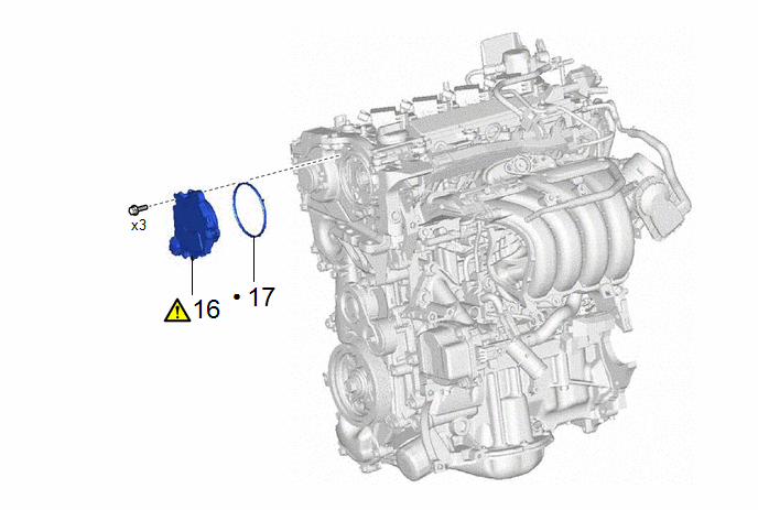
16 | CAM TIMING CONTROL MOTOR WITH EDU ASSEMBLY |
13090D |
|
- | - |
|
17 | CAM TIMING CONTROL MOTOR O-RING |
13090E | - |
- | - |
|
● | Non-reusable part |
- | - |
CAUTION / NOTICE / HINT
NOTICE:
- After the ignition switch is turned off, the radio and display receiver assembly records various types of memory and settings. As a result, after turning the ignition switch off, make sure to wait at least 120 seconds before disconnecting the cable from the negative (-) auxiliary battery terminal.
- This procedure includes the removal of small-head bolts. Refer to Small-Head Bolts of Basic Repair Hint to identify the small-head bolts.
Click here
.gif)
HINT:
When the cable is disconnected/reconnected to the auxiliary battery terminal, systems temporarily stop operating. However, each system has a function that completes learning the first time the system is used.
- Learning completes when vehicle is driven.
Effect/Inoperative Function When Necessary Procedures are not Performed
Necessary Procedures
Link
Front camera system
Drive the vehicle straight ahead at 15 km/h (10 mph) or more for 1 second or more.
Stop and start system
Drive the vehicle until stop and start control is permitted (approximately 5 to 60 minutes)
- Learning completes when vehicle is operated normally
Effect/Inoperative Function When Necessary Procedures are not Performed
Necessary Procedures
Link
Power door lock control system
- Back door opener
Perform door unlock operation with door control switch or electrical key transmitter sub-assembly switch.
Power back door system
Fully close the back door by hand.
HINT:
Initialization is not necessary if the above procedures are performed while the back door is closed.
Air conditioning system
After the ignition switch is turned to ON, the servo motor standard position is recognized.
-
PROCEDURE
1. REMOVE NO. 1 ENGINE UNDER COVER ASSEMBLY
Click here
2. REMOVE REAR ENGINE UNDER COVER RH
Click here
3. REMOVE WINDSHIELD WIPER MOTOR AND LINK ASSEMBLY
Click here
4. REMOVE WATER GUARD PLATE
Click here
5. REMOVE NO. 1 HEATER AIR DUCT SPLASH SHIELD SEAL
Click here
6. REMOVE OUTER COWL TOP PANEL SUB-ASSEMBLY
Click here
7. REMOVE ECM
Click here
8. REMOVE AUXILIARY BATTERY
Click here
9. REMOVE AUXILIARY BATTERY CLAMP SUB-ASSEMBLY
Click here
10. REMOVE FUEL DELIVERY GUARD
Click here
11. INSTALL ENGINE HANGER
|
|
Click here |
12. INSTALL ENGINE SUPPORT BRIDGE
|
|
Click here |
13. SEPARATE RADIATOR RESERVE TANK ASSEMBLY
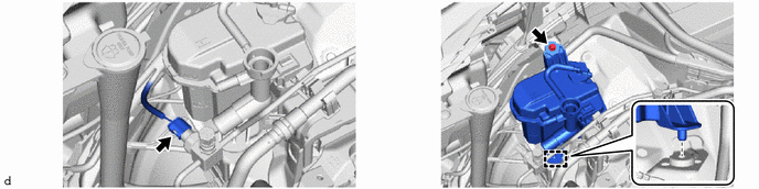
14. SEPARATE NO. 1 COOLER REFRIGERANT HOSE

15. REMOVE ENGINE MOUNTING INSULATOR SUB-ASSEMBLY RH
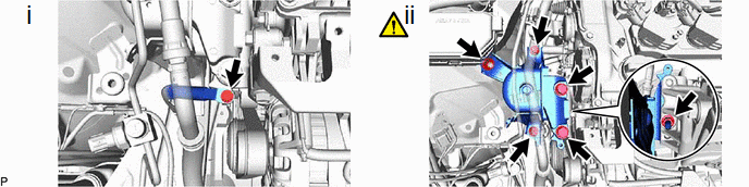
(1) Remove the bolt and separate the No. 2 earth wire from the engine mounting insulator sub-assembly RH.
(2) Remove the 4 bolts, 2 nuts and engine mounting insulator sub-assembly RH from the vehicle body and engine mounting bracket RH.
HINT:
As the engine mounting insulator sub-assembly RH contacts the air conditioning tube assembly and cannot be taken out, move the engine mounting insulator sub-assembly RH to a position where the bolt of the cam timing control motor with EDU assembly can be removed.
16. REMOVE CAM TIMING CONTROL MOTOR WITH EDU ASSEMBLY
|
|
NOTICE: If the cam timing control motor with EDU assembly has been struck or dropped, replace it. |

17. REMOVE CAM TIMING CONTROL MOTOR O-RING