Toyota Corolla Cross: Installation
INSTALLATION
CAUTION / NOTICE / HINT
COMPONENTS (INSTALLATION)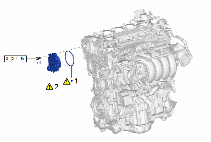
|
Procedure | Part Name Code |
.png) |
.png) |
 |
|---|---|---|---|---|---|
|
1 | CAM TIMING CONTROL MOTOR O-RING |
13090E |
|
- | - |
|
2 | CAM TIMING CONTROL MOTOR WITH EDU ASSEMBLY |
13090D |
|
- | - |
.png) |
N*m (kgf*cm, ft.*lbf): Specified torque |
- | - |
|
Procedure | Part Name Code |
|
|
| |
|---|---|---|---|---|---|
|
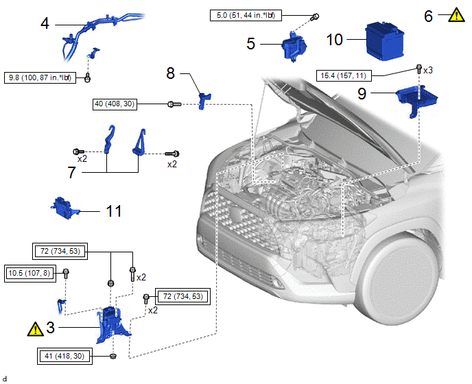
3 | ENGINE MOUNTING INSULATOR SUB-ASSEMBLY RH |
12305 |
|
- | - |
|
4 | NO. 1 COOLER REFRIGERANT HOSE |
- | - |
- | - |
|
5 | RADIATOR RESERVE TANK ASSEMBLY |
16470 | - |
- | - |
|
6 | ENGINE SUPPORT BRIDGE |
- |
|
- | - |
|
7 | ENGINE HANGER |
- | - |
- | - |
|
8 | FUEL DELIVERY GUARD |
23825 | - |
- | - |
|
9 | AUXILIARY BATTERY CLAMP SUB-ASSEMBLY |
74404A | - |
- | - |
|
10 | AUXILIARY BATTERY |
- | - |
- | - |
|
11 | ECM |
89661 | - |
- | - |
.png) |
Tightening torque for "Major areas involving basic vehicle performance such as moving/turning/stopping" : N*m (kgf*cm, ft.*lbf) |
|
N*m (kgf*cm, ft.*lbf): Specified torque |
|
Procedure | Part Name Code |
|
|
| |
|---|---|---|---|---|---|
|
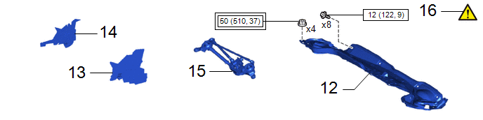
12 | OUTER COWL TOP PANEL SUB-ASSEMBLY |
- | - |
- | - |
|
13 | NO. 1 HEATER AIR DUCT SPLASH SHIELD SEAL |
- | - |
- | - |
|
14 | WATER GUARD PLATE |
- | - |
- | - |
|
15 | WINDSHIELD WIPER MOTOR AND LINK ASSEMBLY |
- | - |
- | - |
|
16 | INSPECT FOR COOLANT LEAK |
- |
|
- | - |
|
|
Tightening torque for "Major areas involving basic vehicle performance such as moving/turning/stopping" : N*m (kgf*cm, ft.*lbf) |
|
N*m (kgf*cm, ft.*lbf): Specified torque |
|
Procedure | Part Name Code |
|
|
| |
|---|---|---|---|---|---|
|
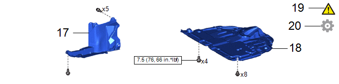
17 | REAR ENGINE UNDER COVER RH |
51443C | - |
- | - |
|
18 | NO. 1 ENGINE UNDER COVER ASSEMBLY |
51410 | - |
- | - |
|
19 | INSPECT FOR ENGINE OIL LEAK |
- |
|
- | - |
|
20 | PERFORM INITIALIZATION |
- | - |
- |
|
|
|
N*m (kgf*cm, ft.*lbf): Specified torque |
- | - |
CAUTION / NOTICE / HINT
NOTICE:
This procedure includes the installation of small-head bolts. Refer to Small-Head Bolts of Basic Repair Hint to identify the small-head bolts.
Click here .gif)
PROCEDURE
1. INSTALL CAM TIMING CONTROL MOTOR O-RING
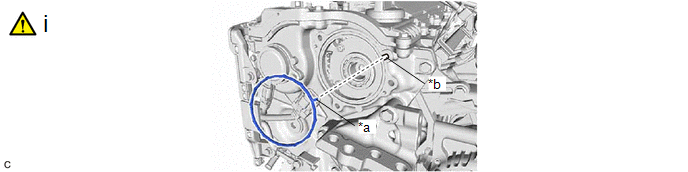
|
*a | Protrusion |
*b | Cutout |
(1) Install a new cam timing control motor O-ring to the No. 2 timing chain cover assembly with the protrusion of the cam timing control motor O-ring oriented as shown in the illustration.
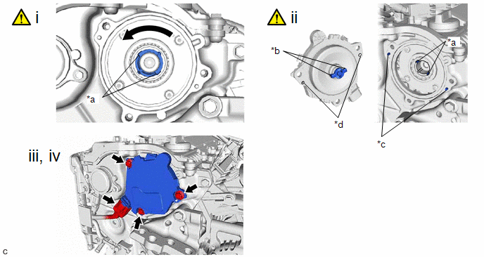
2. INSTALL CAM TIMING CONTROL MOTOR WITH EDU ASSEMBLY
|
|
HINT: Perform "Inspection After Repair" after removing and installing, or replacing the cam timing control motor with EDU assembly. Click here |
|
*a | Cutout |
*b | Joint |
|
*c | Knock Pin |
*d | Pin Hole |
(1) Turn the cutout of the camshaft timing gear assembly eccentric shaft counterclockwise by hand, and set it to the maximum retard angle position.
HINT:
- If a camshaft lobe is opening a valve, the eccentric shaft will be difficult to turn.
- When the cutout of the camshaft timing gear assembly eccentric shaft cannot be turned any farther, it is set to the maximum retard angle.
(2) Install the cam timing control motor with EDU assembly to the No. 2 timing chain cover assembly.
NOTICE:
- When installing, align the joints of the cam timing control motor with EDU assembly with the cutouts of the camshaft timing gear assembly eccentric shaft.
- Align the pin holes of the cam timing control motor with EDU assembly with the knock pins of the No. 2 timing chain cover assembly when installing the cam timing control motor with EDU assembly.
- Make sure the contact surface of the cam timing control motor with EDU assembly (the surface that contacts the No. 2 timing chain cover assembly) is free of foreign matter.
- When installing the cam timing control motor with EDU assembly, do not use excessive force.
- If the cam timing control motor with EDU assembly has been struck or dropped, replace it.
- Do not disassemble the cam timing control motor with EDU assembly. If disassembled, replace it.
(3) Install the 3 bolts.
Torque:
21 N·m {214 kgf·cm, 15 ft·lbf}
(4) Connect the cam timing control motor with EDU assembly connector.
3. INSTALL ENGINE MOUNTING INSULATOR SUB-ASSEMBLY RH
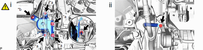
|
*a | Bolt |
*b | Nut (A) |
|
*c | Nut (B) |
- | - |
(1) Install the engine mounting insulator sub-assembly RH to the vehicle body and engine mounting bracket RH with the 4 bolts and 2 nuts.
Torque:
Bolt :
72 N·m {734 kgf·cm, 53 ft·lbf}
Nut (A) :
72 N·m {734 kgf·cm, 53 ft·lbf}
Nut (B) :
41 N·m {418 kgf·cm, 30 ft·lbf}
(2) Install the No. 2 earth wire to the engine mounting insulator sub-assembly RH with the bolt.
Torque:
10.5 N·m {107 kgf·cm, 8 ft·lbf}
4. INSTALL NO. 1 COOLER REFRIGERANT HOSE
Torque:
9.8 N·m {100 kgf·cm, 87 in·lbf}
5. INSTALL RADIATOR RESERVE TANK ASSEMBLY
Torque:
5.0 N·m {51 kgf·cm, 44 in·lbf}
6. REMOVE ENGINE SUPPORT BRIDGE
|
|
Click here |
7. REMOVE ENGINE HANGER
8. INSTALL FUEL DELIVERY GUARD
Click here
9. INSTALL AUXILIARY BATTERY CLAMP SUB-ASSEMBLY
Click here
10. INSTALL AUXILIARY BATTERY
Click here
11. INSTALL ECM
Click here
12. INSTALL OUTER COWL TOP PANEL SUB-ASSEMBLY
Click here
13. INSTALL NO. 1 HEATER AIR DUCT SPLASH SHIELD SEAL
Click here
14. INSTALL WATER GUARD PLATE
Click here
15. INSTALL WINDSHIELD WIPER MOTOR AND LINK ASSEMBLY
Click here
16. INSPECT FOR COOLANT LEAK
Click here
17. INSTALL REAR ENGINE UNDER COVER RH
Click here
18. INSTALL NO. 1 ENGINE UNDER COVER ASSEMBLY
Click here
19. INSPECT FOR ENGINE OIL LEAK
Click here
20. PERFORM INITIALIZATION
(a) Perform "Inspection After Repair" after removing and installing, or replacing the cam timing control motor with EDU assembly.
Click here


