Toyota Corolla Cross: Removal
REMOVAL
CAUTION / NOTICE / HINT
COMPONENTS (REMOVAL)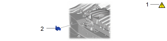
|
Procedure | Part Name Code |
.png) |
.png) |
 |
|---|---|---|---|---|---|
|
1 | PRECAUTION |
- |
|
- | - |
|
2 | SERVICE PLUG GRIP |
G3834 | - |
- | - |
|
Procedure | Part Name Code |
|
|
| |
|---|---|---|---|---|---|
|
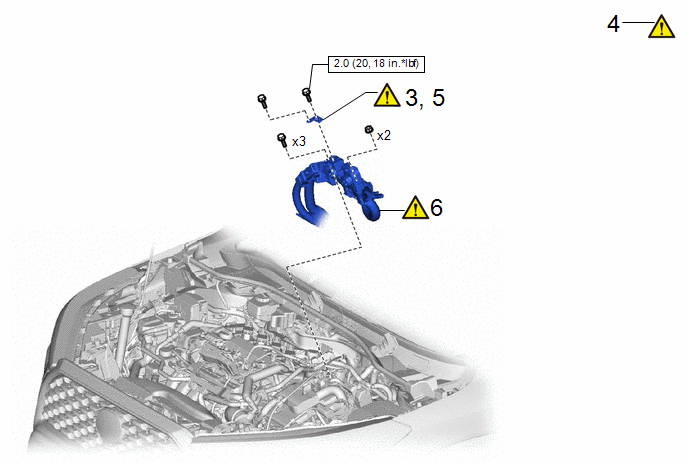
3 | REMOVE CONNECTOR COVER ASSEMBLY |
- |
|
- | - |
|
4 | TERMINAL VOLTAGE |
- |
|
- | - |
|
5 | TEMPORARILY INSTALL CONNECTOR COVER ASSEMBLY |
- |
|
- | - |
|
6 | FLOOR UNDER WIRE |
821H1 |
|
- | - |
.png) |
N*m (kgf*cm, ft.*lbf): Specified torque |
- | - |
|
Procedure | Part Name Code |
|
|
| |
|---|---|---|---|---|---|
|
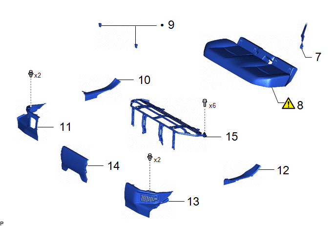
7 | REAR CENTER SEAT OUTER BELT ASSEMBLY |
73350C | - |
- | - |
|
8 | BENCH TYPE REAR SEAT CUSHION ASSEMBLY |
- |
|
- | - |
|
9 | REAR SEAT CUSHION LOCK HOOK |
72693 | - |
- | - |
|
10 | REAR DOOR SCUFF PLATE RH |
67917A | - |
- | - |
|
11 | REAR UNDER SIDE COVER RH |
76973F | - |
- | - |
|
12 | REAR DOOR SCUFF PLATE LH |
67918A | - |
- | - |
|
13 | REAR UNDER SIDE COVER LH |
76974F | - |
- | - |
|
14 | REAR UNDER COVER |
76971G | - |
- | - |
|
15 | REAR SEAT CUSHION LEG SUB-ASSEMBLY |
71033 | - |
- | - |
|
● | Non-reusable part |
- | - |
|
Procedure | Part Name Code |
|
|
| |
|---|---|---|---|---|---|
|
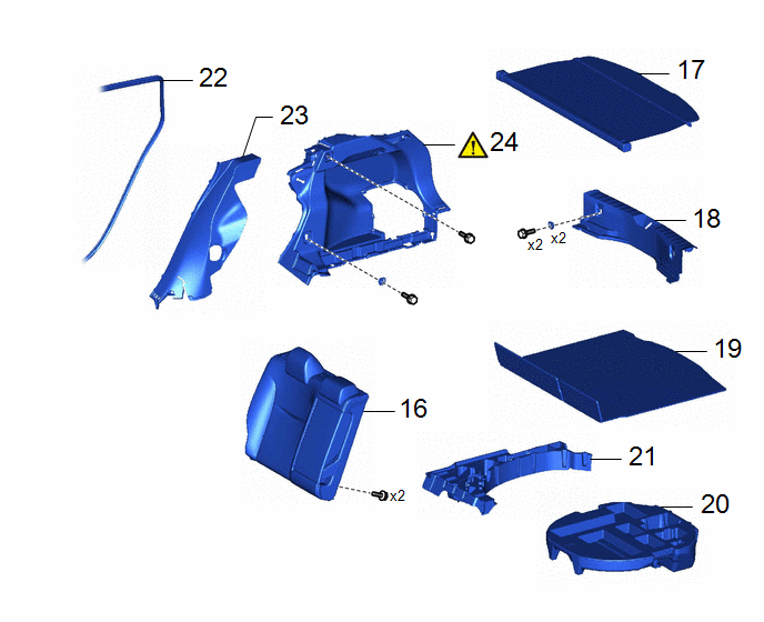
16 | REAR SEATBACK ASSEMBLY RH |
- | - |
- | - |
|
17 | TONNEAU COVER ASSEMBLY |
64910J | - |
- | - |
|
18 | REAR DECK TRIM COVER |
64716D | - |
- | - |
|
19 | DECK BOARD ASSEMBLY |
58410B | - |
- | - |
|
20 | SPARE WHEEL CUSHION |
64777J | - |
- | - |
|
21 | DECK FLOOR BOX RH |
64995 | - |
- | - |
|
22 | REAR DOOR OPENING TRIM WEATHERSTRIP RH |
62331A | - |
- | - |
|
23 | REAR SEAT SIDE GARNISH RH |
62551F | - |
- | - |
|
24 | DECK TRIM SIDE PANEL ASSEMBLY RH |
64730B |
|
- | - |
|
Procedure | Part Name Code |
|
|
| |
|---|---|---|---|---|---|
|
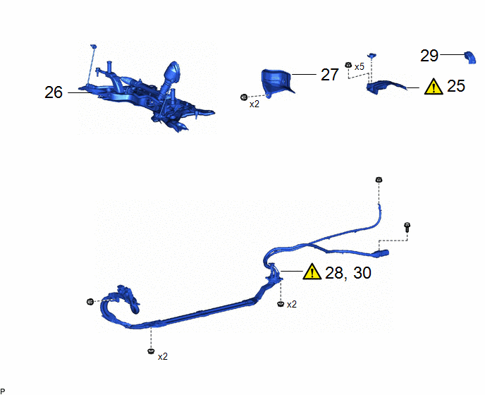
25 | NO. 1 HYBRID BATTERY SHIELD SUB-ASSEMBLY |
G920Q |
|
- | - |
|
26 | FRONT SUSPENSION CROSSMEMBER SUB-ASSEMBLY |
51201 | - |
- | - |
|
27 | DASH PANEL HEAT INSULATOR |
55225C | - |
- | - |
|
28 | DISCONNECT FLOOR UNDER WIRE |
821H1 |
|
- | - |
|
29 | BATTERY TERMINAL CONNECTOR COVER |
28800D | - |
- | - |
|
30 | REMOVE FLOOR UNDER WIRE |
821H1 |
|
- | - |
CAUTION / NOTICE / HINT
CAUTION:
- Orange wire harnesses and connectors indicate high-voltage circuits. To prevent electric shock, always follow the procedure described in the repair manual.
.png)
Click here
.gif)
- To prevent electric shock, wear insulated gloves when working on wire harnesses and components of the high voltage system.
.png)
HINT:
When the cable is disconnected / reconnected to the auxiliary battery terminal, systems temporarily stop operating. However, each system has a function that completes learning the first time the system is used.
- Learning completes when vehicle is driven.
Effect/Inoperative Function When Necessary Procedures are not Performed
Necessary Procedures
Link
Front Camera System
Drive the vehicle straight ahead at 15 km/h (10 mph) or more for 1 second or more.
- Learning completes when vehicle is operated normally
Effect/Inoperative Function When Necessary Procedures are not Performed
Necessary Procedures
Link
Power door lock control system
- Back door opener
Perform door unlock operation with door control switch or electrical key transmitter sub-assembly switch.
Power back door system
Fully close the back door by hand.
HINT:
Initialization is not necessary if the above procedures are performed while the back door is closed.
Air conditioning system
After the ignition switch is turned to ON, the servo motor standard position is recognized.
-
PROCEDURE
1. PRECAUTION
NOTICE:
After turning the ignition switch off, waiting time may be required before disconnecting the cable from the negative (-) auxiliary battery terminal.
Click here
2. REMOVE SERVICE PLUG GRIP
Click here
3. REMOVE CONNECTOR COVER ASSEMBLY
|
|
Click here |
4. CHECK TERMINAL VOLTAGE
|
|
Click here |
5. TEMPORARILY INSTALL CONNECTOR COVER ASSEMBLY
|
|
Click here |
6. DISCONNECT FLOOR UNDER WIRE
|
|
Click here |
7. DISCONNECT REAR CENTER SEAT OUTER BELT ASSEMBLY
Click here
8. REMOVE BENCH TYPE REAR SEAT CUSHION ASSEMBLY
Click here
9. REMOVE REAR SEAT CUSHION LOCK HOOK
Click here
10. REMOVE REAR DOOR SCUFF PLATE RH
Click here
11. REMOVE REAR UNDER SIDE COVER RH
Click here
12. REMOVE REAR DOOR SCUFF PLATE LH
(a) Use the same procedure as for the RH side.
13. REMOVE REAR UNDER SIDE COVER LH
Click here
14. REMOVE REAR UNDER COVER
Click here
15. REMOVE REAR SEAT CUSHION LEG SUB-ASSEMBLY
Click here
16. REMOVE REAR SEATBACK ASSEMBLY RH
Click here
17. REMOVE TONNEAU COVER ASSEMBLY
Click here
18. REMOVE REAR DECK TRIM COVER
Click here
19. REMOVE DECK BOARD ASSEMBLY
Click here
20. REMOVE SPARE WHEEL CUSHION
Click here
21. REMOVE DECK FLOOR BOX RH
Click here
22. SEPARATE REAR DOOR OPENING TRIM WEATHERSTRIP RH
Click here
23. REMOVE REAR SEAT SIDE GARNISH RH
Click here
24. REMOVE DECK TRIM SIDE PANEL ASSEMBLY RH
|
|
Click here |
25. REMOVE NO. 1 HYBRID BATTERY SHIELD SUB-ASSEMBLY
|
|
Click here |
26. REMOVE FRONT SUSPENSION CROSSMEMBER SUB-ASSEMBLY
Click here
27. REMOVE DASH PANEL HEAT INSULATOR

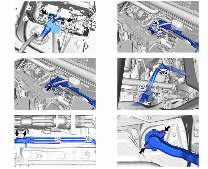
28. DISCONNECT FLOOR UNDER WIRE
|
|
CAUTION: Wear insulated gloves. NOTICE: Insulate each disconnected high-voltage connector with insulating tape. Wrap the connector from the wire harness side to the end of the connector. |
|
*a | Shield Ground |
- | - |
29. REMOVE BATTERY TERMINAL CONNECTOR COVER

30. REMOVE FLOOR UNDER WIRE
|
|
CAUTION: Wear insulated gloves. NOTICE: Insulate each disconnected high-voltage connector with insulating tape. Wrap the connector from the wire harness side to the end of the connector. |
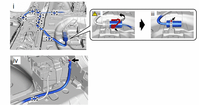
(1) Disengage the 8 clamps.
(2) Move the lock lever as shown in the illustration and disconnect the rear traction motor cable connector.
(3) Remove the bolt.
(4) Disengage the clamp and remove the nut.


