Toyota Corolla Cross: Installation
INSTALLATION
CAUTION / NOTICE / HINT
COMPONENTS (INSTALLATION)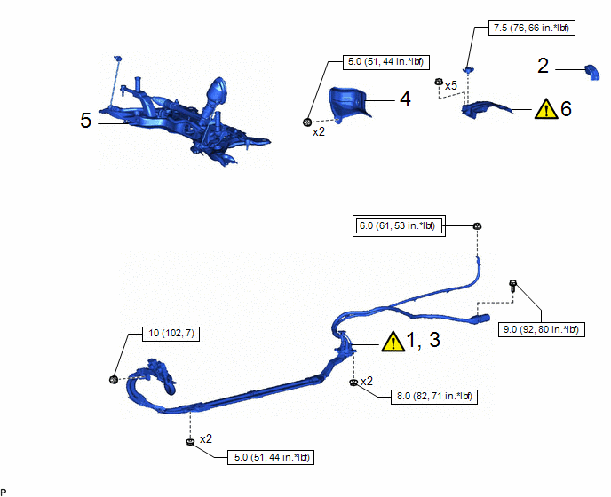
|
Procedure | Part Name Code |
.png) |
.png) |
 |
|---|---|---|---|---|---|
|
1 | INSTALL FLOOR UNDER WIRE |
821H1 |
|
- | - |
|
2 | BATTERY TERMINAL CONNECTOR COVER |
28800D | - |
- | - |
|
3 | CONNECT FLOOR UNDER WIRE |
821H1 |
|
- | - |
|
4 | DASH PANEL HEAT INSULATOR |
55225C | - |
- | - |
|
5 | FRONT SUSPENSION CROSSMEMBER SUB-ASSEMBLY |
51201 | - |
- | - |
|
6 | NO. 1 HYBRID BATTERY SHIELD SUB-ASSEMBLY |
G920Q |
|
- | - |
.png) |
Tightening torque for "Major areas involving basic vehicle performance such as moving/turning/stopping" : N*m (kgf*cm, ft.*lbf) |
.png) |
N*m (kgf*cm, ft.*lbf): Specified torque |
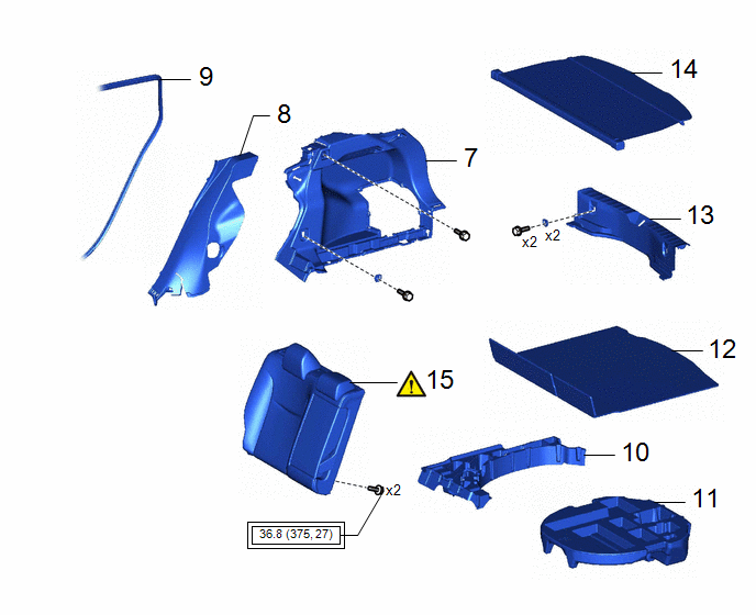
|
Procedure | Part Name Code |
.png) |
.png) |
 |
|---|---|---|---|---|---|
|
7 | DECK TRIM SIDE PANEL ASSEMBLY RH |
64730B | - |
- | - |
|
8 | REAR SEAT SIDE GARNISH RH |
62551F | - |
- | - |
|
9 | REAR DOOR OPENING TRIM WEATHERSTRIP RH |
62331A | - |
- | - |
|
10 | DECK FLOOR BOX RH |
64995 | - |
- | - |
|
11 | SPARE WHEEL CUSHION |
64777J | - |
- | - |
|
12 | DECK BOARD ASSEMBLY |
58410B | - |
- | - |
|
13 | REAR DECK TRIM COVER |
64716D | - |
- | - |
|
14 | TONNEAU COVER ASSEMBLY |
64910J | - |
- | - |
|
15 | REAR SEATBACK ASSEMBLY RH |
- |
|
- | - |
.png) |
Tightening torque for "Major areas involving basic vehicle performance such as moving/turning/stopping" : N*m (kgf*cm, ft.*lbf) |
- | - |
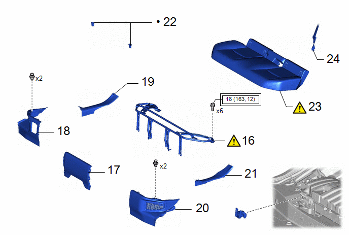
|
Procedure | Part Name Code |
.png) |
.png) |
 |
|---|---|---|---|---|---|
|
16 | REAR SEAT CUSHION LEG SUB-ASSEMBLY |
71033 |
|
- | - |
|
17 | REAR UNDER COVER |
76971G | - |
- | - |
|
18 | REAR UNDER SIDE COVER RH |
76973F | - |
- | - |
|
19 | REAR DOOR SCUFF PLATE RH |
67917A | - |
- | - |
|
20 | REAR UNDER SIDE COVER LH |
76974F | - |
- | - |
|
21 | REAR DOOR SCUFF PLATE LH |
67918A | - |
- | - |
|
22 | REAR SEAT CUSHION LOCK HOOK |
72693 | - |
- | - |
|
23 | BENCH TYPE REAR SEAT CUSHION ASSEMBLY |
- |
|
- | - |
|
24 | REAR CENTER SEAT OUTER BELT ASSEMBLY |
73350C | - |
- | - |
.png) |
Tightening torque for "Major areas involving basic vehicle performance such as moving/turning/stopping" : N*m (kgf*cm, ft.*lbf) |
● | Non-reusable part |
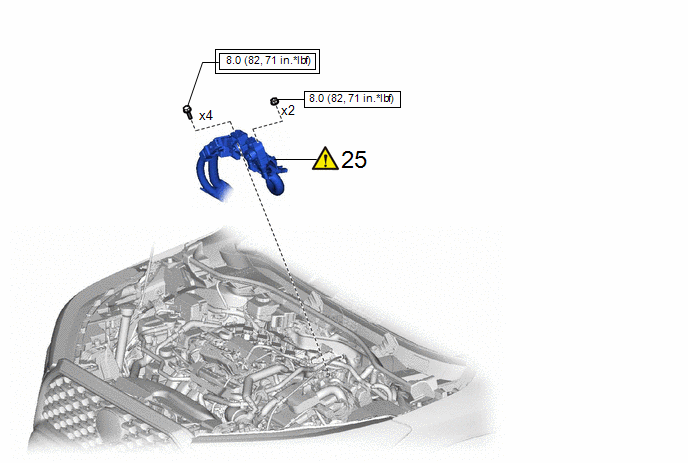
|
Procedure | Part Name Code |
.png) |
.png) |
 |
|---|---|---|---|---|---|
|
25 | FLOOR UNDER WIRE |
821H1 |
|
- | - |
.png) |
Tightening torque for "Major areas involving basic vehicle performance such as moving/turning/stopping" : N*m (kgf*cm, ft.*lbf) |
.png) |
N*m (kgf*cm, ft.*lbf): Specified torque |

|
Procedure | Part Name Code |
.png) |
.png) |
 |
|---|---|---|---|---|---|
|
26 | SERVICE PLUG GRIP |
G3834 | - |
- | - |
PROCEDURE
1. INSTALL FLOOR UNDER WIRE
.png) |
CAUTION: Be sure to wear insulated gloves. |

(1) Install the nut and engage the clamp.
Torque:
6.0 N·m {61 kgf·cm, 53 in·lbf}

(1) Install the bolt.
Torque:
9.0 N·m {92 kgf·cm, 80 in·lbf}
(2) Connect the rear traction motor cable connector and move the lock lever to lock them.
(3) Engage the 8 clamps.
2. INSTALL BATTERY TERMINAL CONNECTOR COVER
3. CONNECT FLOOR UNDER WIRE
.png) |
CAUTION: Be sure to wear insulated gloves. |
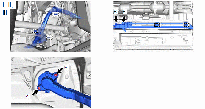
(1) Insert the floor under wire into the floor panel hole and engage the grommet.
(2) Install the 4 nuts.
Torque:
Nut A :
8.0 N·m {82 kgf·cm, 71 in·lbf}
Nut B :
5.0 N·m {51 kgf·cm, 44 in·lbf}
(3) Engage the 5 clamps.

(1) Connect the engine room main wire with the nut.
Torque:
10 N·m {102 kgf·cm, 7 ft·lbf}
(2) Engage the 2 claws to install the floor under wire terminal cover.

|
*a | Shield Ground |
- | - |
(1) Connect the shield ground to the HV battery.
(2) Connect the 2 HV battery junction block assembly connectors.
NOTICE:
Make sure that the connectors are connected securely.
4. INSTALL DASH PANEL HEAT INSULATOR
Torque:
5.0 N·m {51 kgf·cm, 44 in·lbf}
5. INSTALL FRONT SUSPENSION CROSSMEMBER SUB-ASSEMBLY
Click here
.gif)
6. INSTALL NO. 1 HYBRID BATTERY SHIELD SUB-ASSEMBLY
.png) |
Click here |
7. INSTALL DECK TRIM SIDE PANEL ASSEMBLY RH
Click here
.gif)
8. INSTALL REAR SEAT SIDE GARNISH RH
9. INSTALL REAR DOOR OPENING TRIM WEATHERSTRIP RH
10. INSTALL DECK FLOOR BOX RH
11. INSTALL SPARE WHEEL CUSHION
12. INSTALL DECK BOARD ASSEMBLY
13. INSTALL REAR DECK TRIM COVER
14. INSTALL TONNEAU COVER ASSEMBLY
15. INSTALL REAR SEATBACK ASSEMBLY RH
.png) |
Click here |
16. INSTALL REAR SEAT CUSHION LEG SUB-ASSEMBLY
Click here
.gif)
17. INSTALL REAR UNDER COVER
Click here
.gif)
18. INSTALL REAR UNDER SIDE COVER RH
19. INSTALL REAR DOOR SCUFF PLATE RH
20. INSTALL REAR UNDER SIDE COVER LH
21. INSTALL REAR DOOR SCUFF PLATE LH
22. INSTALL REAR SEAT CUSHION LOCK HOOK
Click here .gif)
23. INSTALL BENCH TYPE REAR SEAT CUSHION ASSEMBLY
Click here .gif)
24. CONNECT REAR CENTER SEAT OUTER BELT ASSEMBLY
Click here .gif)
25. CONNECT FLOOR UNDER WIRE
.png) |
Click here |
26. INSTALL SERVICE PLUG GRIP
Click here
.gif)


