Toyota Corolla Cross: Removal
REMOVAL
CAUTION / NOTICE / HINT
COMPONENTS (REMOVAL)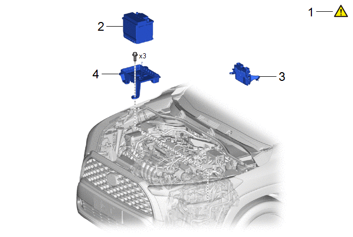
|
Procedure |
Part Name Code |
.png) |
.png) |
.png) |
|
|---|---|---|---|---|---|
|
1 |
SECURE VEHICLE |
- |
|
- |
- |
|
2 |
AUXILIARY BATTERY |
- |
- |
- |
- |
|
3 |
ECM |
89661 |
- |
- |
- |
|
4 |
BATTERY CLAMP SUB-ASSEMBLY |
74404A |
- |
- |
- |
|
Procedure |
Part Name Code |
|
|
|
|
|---|---|---|---|---|---|
|
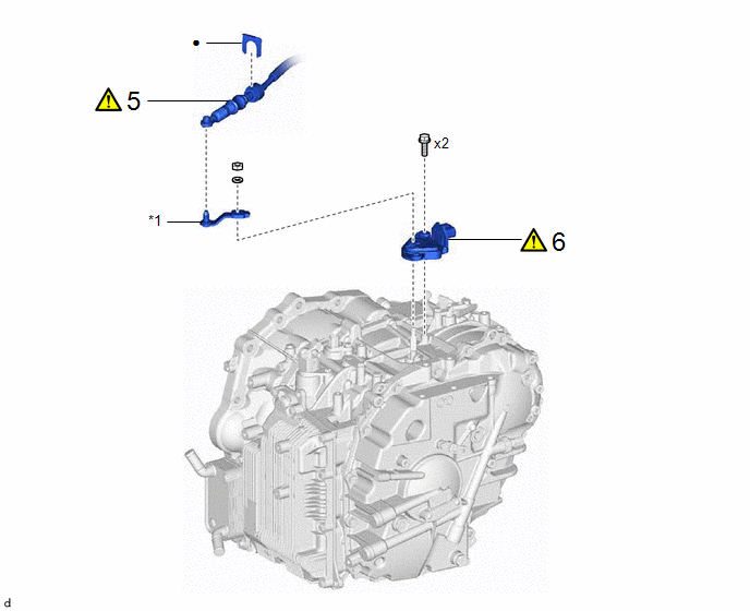
5 |
TRANSMISSION CONTROL CABLE ASSEMBLY |
33820B |
|
- |
- |
|
6 |
PARK/NEUTRAL POSITION SWITCH ASSEMBLY |
84540 |
|
- |
- |
|
*1 |
TRANSMISSION CONTROL SHAFT LEVER |
- |
- |
|
● |
Non-reusable part |
- |
- |
CAUTION / NOTICE / HINT
HINT:
When the cable is disconnected / reconnected to the auxiliary battery terminal, systems temporarily stop operating. However, each system has a function that completes learning the first time the system is used.
- Learning completes when vehicle is driven
Effect/Inoperative Function When Necessary Procedures are not Performed
Necessary Procedures
Link
Front camera system
Drive the vehicle straight ahead at 15 km/h (10 mph) or more for 1 second or more.
.gif)
Stop and start system
Drive the vehicle until stop and start control is permitted (approximately 5 to 60 minutes)
- Learning completes when vehicle is operated normally
Effect/Inoperative Function When Necessary Procedures are not Performed
Necessary Procedures
Link
Power door lock control system
- Back door opener
Perform door unlock operation with door control switch or electrical key transmitter sub-assembly switch.
Power back door system
Fully close the back door by hand.
HINT:
Initialization is not necessary if the above procedures are performed while the back door is closed.
Air conditioning system
After the ignition switch is turned to ON, the servo motor standard position is recognized.
-
PROCEDURE
1. SECURE VEHICLE
|
|
Click here |
2. REMOVE AUXILIARY BATTERY
Click here
3. REMOVE ECM
Click here
4. REMOVE BATTERY CLAMP SUB-ASSEMBLY
Click here
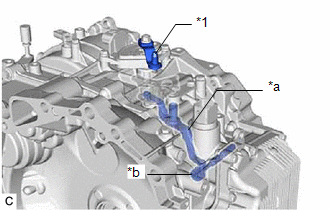
5. DISCONNECT TRANSMISSION CONTROL CABLE ASSEMBLY
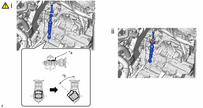
|
*a |
Clip |
*b |
45° to 60° |
(1) While disengaging the clip as shown in the illustration, disconnect the transmission control cable assembly from the transmission control shaft lever together with the clip.
(2) Remove the clip and disconnect the transmission control cable assembly from the No. 1 transmission control cable bracket.
6. REMOVE PARK/NEUTRAL POSITION SWITCH ASSEMBLY
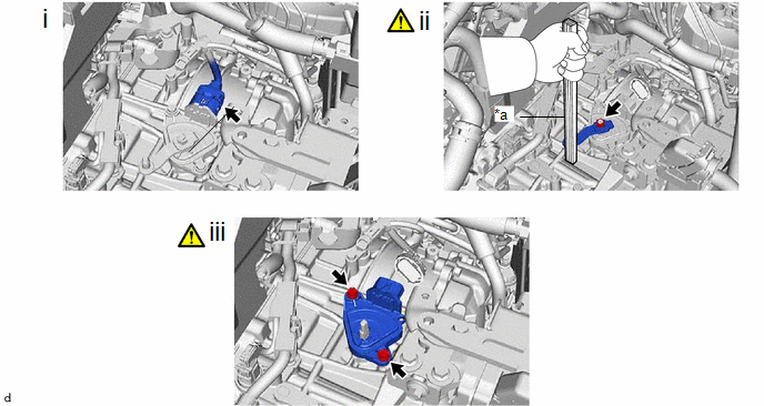
|
*a |
Piece of Wood or Equivalent |
- |
- |
(1) Disconnect the park/neutral position switch assembly connector.
(2) Using a piece of wood or equivalent to secure the transmission control shaft lever to prevent it from rotating, remove the nut, washer and transmission control shaft lever from the manual valve lever shaft.
NOTICE:
If the transmission control shaft lever is not secured when loosening the nut, the manual valve link lever sub-assembly may separate from the manual valve.
|
*1 |
Transmission Control Shaft Lever |
|
*a |
Manual Valve Link Lever Sub-assembly |
|
*b |
Manual Valve |
(3) Remove the 2 bolts and park/neutral position switch assembly from the transaxle case sub-assembly.
NOTICE:
Before removing the park/neutral position switch assembly, remove any dirt or rust on the installation portion of the manual valve lever shaft. Be sure to remove the park/neutral position switch assembly straight along the manual valve lever shaft while being careful not to deform the plate spring that supports the manual valve lever shaft. If the plate spring is deformed, the park/neutral position switch assembly cannot be reinstalled correctly.


