Toyota Corolla Cross: Installation
INSTALLATION
CAUTION / NOTICE / HINT
COMPONENTS (INSTALLATION)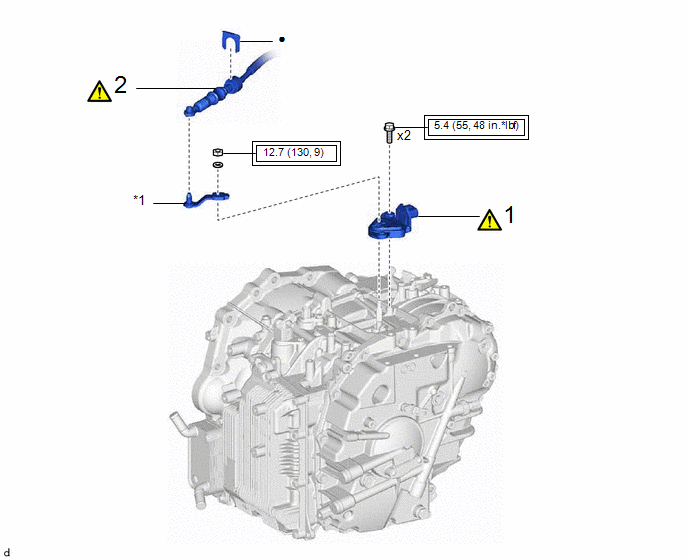
|
Procedure |
Part Name Code |
.png) |
.png) |
.png) |
|
|---|---|---|---|---|---|
|
1 |
PARK/NEUTRAL POSITION SWITCH ASSEMBLY |
84540 |
|
- |
- |
|
2 |
TRANSMISSION CONTROL CABLE ASSEMBLY |
33820B |
|
- |
- |
.png) |
Tightening torque for "Major areas involving basic vehicle performance such as moving/turning/stopping": N*m (kgf*cm, ft.*lbf) |
● |
Non-reusable part |
|
Procedure |
Part Name Code |
|
|
|
|
|---|---|---|---|---|---|
|
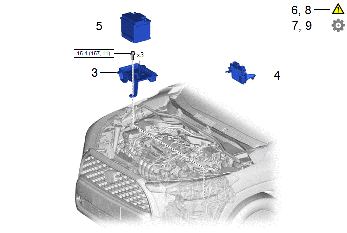
3 |
BATTERY CLAMP SUB-ASSEMBLY |
74404A |
- |
- |
- |
|
4 |
ECM |
89661 |
- |
- |
- |
|
5 |
AUXILIARY BATTERY |
- |
- |
- |
- |
|
6 |
INSPECT SHIFT LEVER POSITION |
- |
|
- |
- |
|
7 |
ADJUST SHIFT LEVER POSITION |
- |
- |
- |
|
|
8 |
INSPECT PARK/NEUTRAL POSITION SWITCH ASSEMBLY |
- |
|
- |
- |
|
9 |
ADJUST PARK/NEUTRAL POSITION SWITCH ASSEMBLY |
- |
- |
- |
|
.png) |
N*m (kgf*cm, ft.*lbf): Specified torque |
- |
- |
PROCEDURE
1. INSTALL PARK/NEUTRAL POSITION SWITCH ASSEMBLY
|
*a |
N |
*b |
Protrusion |
(1) Temporarily install the park/neutral position switch assembly to the transaxle case sub-assembly with the 2 bolts.
(2) Temporarily install the transmission control shaft lever to the manual valve lever shaft.
(3) Turn the transmission control shaft lever clockwise until it stops, then turn it counterclockwise 2 notches.
NOTICE:
If the transmission control shaft lever is turned counterclockwise more than necessary, manual valve link lever sub-assembly may separate from the manual valve.
.png)
|
*1 |
Transmission Control Shaft Lever |
|
*a |
Manual Valve Link Lever Sub-assembly |
|
*b |
Manual Valve |
(4) Remove the transmission control shaft lever from the manual valve lever shaft.
(5) Align the protrusions of the park/neutral position switch assembly as shown in the illustration.
(6) Hold the park/neutral position switch assembly in that position and tighten the 2 bolts.
Torque:
5.4 N·m {55 kgf·cm, 48 in·lbf}
(7) Install the transmission control shaft lever to the manual valve lever shaft with the washer and nut.
Torque:
12.7 N·m {130 kgf·cm, 9 ft·lbf}
NOTICE:
Be careful of the direction of the transmission control shaft lever.
(8) Connect the park/neutral position switch connector.
2. CONNECT TRANSMISSION CONTROL CABLE ASSEMBLY
|
|
NOTICE: Before connecting the transmission control cable assembly, check that the shift lever is in N. |
|
*a |
N |
*b |
Correct |
|
*c |
Incorrect |
- |
- |
(1) Turn the transmission control shaft lever clockwise until it stops, then turn it counterclockwise 2 notches.
NOTICE:
If the transmission control shaft lever is turned counterclockwise more than necessary, manual valve link lever sub-assembly may separate from the manual valve.
|
*1 |
Transmission Control Shaft Lever |
|
*a |
Manual Valve Link Lever Sub-assembly |
|
*b |
Manual Valve |
(2) Connect the transmission control cable assembly to the No. 1 transmission control cable bracket with a new clip.
(3) Connect the transmission control cable assembly to the transmission control shaft lever as shown in the illustration.
3. INSTALL BATTERY CLAMP SUB-ASSEMBLY
Click here .gif)
4. INSTALL ECM
Click here
5. INSTALL AUXILIARY BATTERY
Click here
6. INSPECT SHIFT LEVER POSITION
Click here
7. ADJUST SHIFT LEVER POSITION
Click here
8. INSPECT PARK/NEUTRAL POSITION SWITCH ASSEMBLY
Click here
9. ADJUST PARK/NEUTRAL POSITION SWITCH ASSEMBLY
Click here


