Toyota Corolla Cross: Removal
REMOVAL
CAUTION / NOTICE / HINT
COMPONENTS (REMOVAL)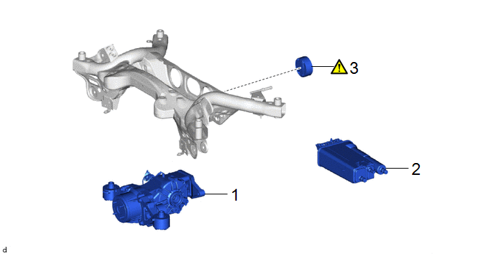
|
Procedure |
Part Name Code |
 |
 |
 |
|
|---|---|---|---|---|---|
|
1 |
REAR DIFFERENTIAL CARRIER ASSEMBLY |
41110 |
- |
- |
- |
|
2 |
CHARCOAL CANISTER ASSEMBLY |
77740 |
- |
- |
- |
|
3 |
REAR NO. 1 DIFFERENTIAL MOUNT CUSHION |
41651 |
|
- |
- |
CAUTION / NOTICE / HINT
The necessary procedures (adjustment, calibration, initialization, or registration) that must be performed after parts are removed and installed, or replaced during the rear No. 1 differential mount cushion removal/installation are shown below.
Necessary Procedures After Parts Removed/Installed/Replaced|
Replacement Part or Procedure |
Necessary Procedures |
Effect/Inoperative Function When Necessary Procedures are not Performed |
Link |
|---|---|---|---|
|
Rear wheel alignment adjustment |
|
|
|
|
Reset memory |
Dynamic torque control AWD system |
|
|
|
Suspension, tires, etc. |
Rear television camera assembly optical axis (Back camera position setting) |
Parking assist monitor system |
|
|
Initialize headlight ECU sub-assembly LH |
Automatic headlight beam level control system |
|
PROCEDURE
1. REMOVE REAR DIFFERENTIAL CARRIER ASSEMBLY
Click here .gif)
2. REMOVE CHARCOAL CANISTER ASSEMBLY
Click here
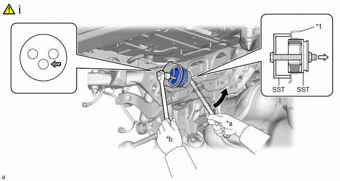
3. REMOVE REAR NO. 1 DIFFERENTIAL MOUNT CUSHION
|
*1 |
Rear Suspension Member Sub-assembly |
- |
- |
|
*a |
Turn |
*b |
Hold |
 |
Front of Vehicle |
 |
SST Bolt Position |
(1) Using SST, remove the rear No. 1 differential mount cushion from the rear suspension member sub-assembly.
SST: 09316-20011
SST: 09570-24011
NOTICE:
- Do not bring SST (09316-20011) into contact with the rear suspension member sub-assembly.
- Before using SST, apply grease to SST bolt.
- Be sure to use the correct combination of SST.
- Make sure that SST contacts the entire circumference of the rear No. 1 differential mount cushion.
- Do not tilt the bolt of SST.


