Toyota Corolla Cross: Reassembly
REASSEMBLY
CAUTION / NOTICE / HINT
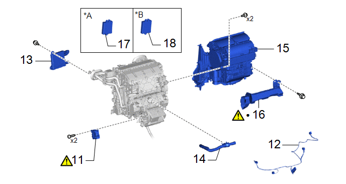
COMPONENTS (REASSEMBLY)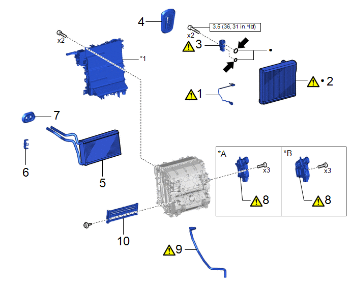
|
Procedure | Part Name Code |
.png) |
.png) |
 |
|---|---|---|---|---|---|
|
1 | NO. 1 COOLER THERMISTOR |
88625 |
|
- | - |
|
2 | NO. 1 COOLER EVAPORATOR SUB-ASSEMBLY |
88501 |
|
- | - |
|
3 | COOLER EXPANSION VALVE |
88515 |
|
- | - |
|
4 | COOLER PIPE GROMMET |
88897K | - |
- | - |
|
5 | HEATER RADIATOR UNIT SUB-ASSEMBLY |
87107A | - |
- | - |
|
6 | HEATER CLAMP |
87124B | - |
- | - |
|
7 | HEATER PIPE GROMMET |
88897M | - |
- | - |
|
8 | NO. 1 AIR CONDITIONING RADIATOR DAMPER SERVO SUB-ASSEMBLY |
87050C |
|
- | - |
|
9 | DRAIN COOLER HOSE |
88539J |
|
- | - |
|
10 | HEATER COVER |
87114B | - |
- | - |
.gif)
|
*A | for Single Type |
*B | for Dual Type |
|
*1 | UPPER HEATER CASE |
- | - |
.png) |
N*m (kgf*cm, ft.*lbf): Specified torque |
● | Non-reusable part |
.png) |
for Gasoline Model: Compressor oil ND-OIL 12 or equivalent for HEV Model: Compressor oil ND-OIL 11 or equivalent |
- | - |
|
Procedure | Part Name Code |
|
|
| |
|---|---|---|---|---|---|
|
11 | NO. 2 AIR CONDITIONING RADIATOR DAMPER SERVO SUB-ASSEMBLY |
87050D |
|
- | - |
|
12 | AIR CONDITIONING HARNESS ASSEMBLY |
82210K | - |
- | - |
|
13 | AIR CONDITIONING AMPLIFIER ASSEMBLY |
88650N | - |
- | - |
|
14 | ASPIRATOR |
88897P | - |
- | - |
|
15 | BLOWER ASSEMBLY |
87130D | - |
- | - |
|
16 | NO. 2 AIR DUCT |
87211A |
|
- | - |
|
17 | TRANSPONDER KEY ECU ASSEMBLY |
89780 | - |
- | - |
|
18 | IMMOBILIZER CODE ECU |
89784 | - |
- | - |
|
*A | w/ Transponder ECU |
*B | w/ ID Code Box |
|
● | Non-reusable part |
- | - |
PROCEDURE
1. INSTALL NO. 1 COOLER THERMISTOR
|
|
Click here |
2. INSTALL NO. 1 COOLER EVAPORATOR SUB-ASSEMBLY
|
|
NOTICE: When the No. 1 cooler evaporator sub-assembly is removed, make sure to install a new one. The No. 1 cooler evaporator sub-assembly cannot be reused. |
3. INSTALL COOLER EXPANSION VALVE
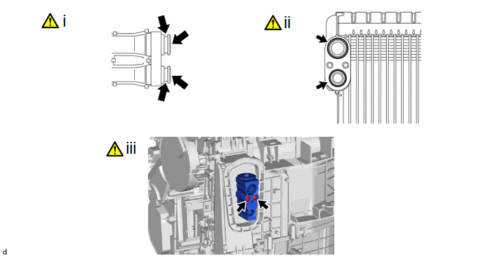
(1) Sufficiently apply compressor oil to 2 new O-rings and the fitting surfaces of the No. 1 cooler evaporator sub-assembly.
Compressor Oil:
for Gasoline Model:
ND-OIL 12 or equivalent
for HEV Model:
ND-OIL 11 or equivalent
(2) Install the 2 O-rings to the No. 1 cooler evaporator sub-assembly.
NOTICE:
Keep the O-rings and O-ring fitting surfaces free of foreign matter.
(3) Using a 4 mm hexagon socket wrench, install the cooler expansion valve with the 2 bolts.
Torque:
3.5 N·m {36 kgf·cm, 31 in·lbf}
4. INSTALL COOLER PIPE GROMMET
5. INSTALL HEATER RADIATOR UNIT SUB-ASSEMBLY
6. INSTALL HEATER CLAMP
7. INSTALL HEATER PIPE GROMMET
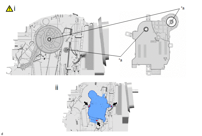
8. INSTALL NO. 1 AIR CONDITIONING RADIATOR DAMPER SERVO SUB-ASSEMBLY
(a) for Single Type:
|
*a | Align shapes |
- | - |
(1) Move the gear of the air conditioner radiator assembly so that the shape of the center gear portion of the air conditioner radiator assembly is aligned with the sensor shaft and output shaft of the No. 1 air conditioning radiator damper servo sub-assembly, and temporarily install the No. 1 air conditioning radiator damper servo sub-assembly as shown in the illustration.
(2) Install the No. 1 air conditioning radiator damper servo sub-assembly with the 3 screws.
(b) for Dual Type:
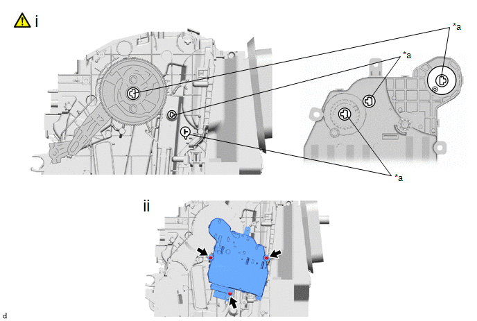
|
*a | Align shapes |
- | - |
(1) Move the gear of the air conditioner radiator assembly so that the shape of the center gear portion of the air conditioner radiator assembly is aligned with the sensor shaft and output shaft of the No. 1 air conditioning radiator damper servo sub-assembly, and temporarily install the No. 1 air conditioning radiator damper servo sub-assembly as shown in the illustration.
(2) Install the No. 1 air conditioning radiator damper servo sub-assembly with the 3 screws.
9. INSTALL DRAIN COOLER HOSE
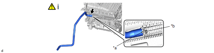
|
*a | Hose Notch |
*b | Rib |
(1) Align the hose notch with the rib as shown in the illustration and install the drain cooler hose.
10. INSTALL HEATER COVER
11. INSTALL NO. 2 AIR CONDITIONING RADIATOR DAMPER SERVO SUB-ASSEMBLY
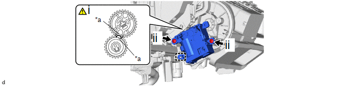
|
*a | Reference Point |
- | - |
(1) Using the reference points, engage the guide to install the No. 2 air conditioning radiator damper servo sub-assembly.
(2) Install the 2 screws.
12. INSTALL AIR CONDITIONING HARNESS ASSEMBLY
13. INSTALL AIR CONDITIONING AMPLIFIER ASSEMBLY
14. INSTALL ASPIRATOR
15. INSTALL BLOWER ASSEMBLY
16. INSTALL NO. 2 AIR DUCT
|
|
NOTICE: If the fitting part of the No. 2 air duct has been cracked or deformed during removal, make sure to replace the air duct with a new one. Failure to do so may cause the No. 2 air duct to fall off or noise to occur. |
17. INSTALL TRANSPONDER KEY ECU ASSEMBLY (w/ Transponder ECU)
18. INSTALL IMMOBILIZER CODE ECU (w/ ID Code Box)


