Toyota Corolla Cross: Ambient Temperature Sensor
Removal
REMOVAL
CAUTION / NOTICE / HINT
COMPONENTS (REMOVAL)

|
Procedure | Part Name Code |
.png) |
.png) |
.png) |
|
1 | FRONT BUMPER ASSEMBLY |
- | - |
- | - |
|
2 | THERMISTOR ASSEMBLY |
88790B | - |
- | - |
PROCEDURE
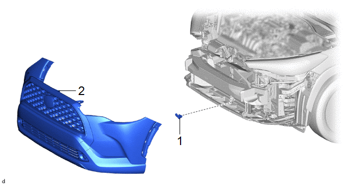
1. REMOVE FRONT BUMPER ASSEMBLY
- except Sport Package:
Click here .gif)
- for Sport Package:
Click here
2. REMOVE THERMISTOR ASSEMBLY

Inspection
INSPECTION
PROCEDURE
1. INSPECT THERMISTOR ASSEMBLY
(a) Check the resistance.
| (1) Measure the resistance according to the value(s) in the table below.
Standard Resistance: |
Tester Connection | Condition |
Specified Condition | |
A3-1 - A3-2 | 10°C (50°F) |
3.00 to 3.73 kΩ | | A3-1 - A3-2 |
15°C (59°F) | 2.45 to 2.88 kΩ | |
A3-1 - A3-2 | 20°C (68°F) |
1.95 to 2.30 kΩ | | A3-1 - A3-2 |
25°C (77°F) | 1.60 to 1.80 kΩ | |
A3-1 - A3-2 | 30°C (86°F) |
1.28 to 1.47 kΩ | | A3-1 - A3-2 |
35°C (95°F) | 1.00 to 1.22 kΩ | |
A3-1 - A3-2 | 40°C (104°F) |
0.80 to 1.00 kΩ | | A3-1 - A3-2 |
45°C (113°F) | 0.65 to 0.85 kΩ | |
A3-1 - A3-2 | 50°C (122°F) |
0.50 to 0.70 kΩ | | A3-1 - A3-2 |
55°C (131°F) | 0.44 to 0.60 kΩ | |
A3-1 - A3-2 | 60°C (140°F) |
0.36 to 0.50 kΩ |
NOTICE:
- Hold the sensor only by its connector. Touching the sensing portion may change the resistance value.
- When measuring, the sensor temperature must be the same as the ambient temperature.
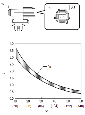
HINT: As the temperature increases, the resistance decreases (see the graph).
If the result is not as specified, replace the thermistor assembly. |
 |
|
*a | Component without harness connected
(Thermistor Assembly) | |
*b | Sensing Portion | |
*c | Resistance (kΩ) | |
*d | Temperature (°C (°F)) | |
*e | Allowable Range | | |
Installation
INSTALLATION
CAUTION / NOTICE / HINT
COMPONENTS (INSTALLATION)
|
Procedure | Part Name Code |
.png) |
.png) |
.png) |
|
1 | THERMISTOR ASSEMBLY |
88790B | - |
- | - |
|
2 | FRONT BUMPER ASSEMBLY |
- | - |
- | - |
PROCEDURE
1. INSTALL THERMISTOR ASSEMBLY
2. INSTALL FRONT BUMPER ASSEMBLY
- except Sport Package:
Click here .gif)
- for Sport Package:
Click here
READ NEXT:
REMOVAL CAUTION / NOTICE / HINT COMPONENTS (REMOVAL)
Procedure Part Name Code
1 AIR CONDITIONER UNIT ASSEMBLY
- -
- -
2 NO. 2 AIR DUCT
DISASSEMBLY CAUTION / NOTICE / HINT COMPONENTS (DISASSEMBLY)
Procedure Part Name Code
1 AIR FILTER COVER PLATE
88899M -
- -
2 CLEAN AIR
SEE MORE:
DESCRIPTION The high-pressure direct injection fuel system consists of a spill control valve, check valve, fuel relief valve, fuel pressure sensor (for high pressure side), fuel pump assembly (for high pressure side) and direct fuel injector assemblies. The spill control valve adjusts the return vol
REPLACEMENT
CAUTION / NOTICE / HINT
The necessary procedures (adjustment, calibration, initialization, or registration)
that must be performed after parts are removed and installed, or replaced during
the CVT fluid replacement are shown below.
Necessary Procedure After Parts Removed/Installed


