Toyota Corolla Cross: Removal
REMOVAL
CAUTION / NOTICE / HINT
COMPONENTS (REMOVAL)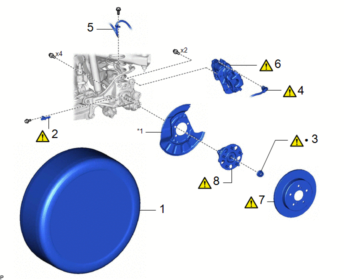
|
Procedure |
Part Name Code |
.png) |
.png) |
.png) |
|
|---|---|---|---|---|---|
|
1 |
REAR WHEEL |
- |
- |
- |
- |
|
2 |
REAR SKID CONTROL SENSOR |
89544E |
|
- |
- |
|
3 |
REAR AXLE SHAFT NUT |
42312B |
|
- |
- |
|
4 |
NO. 2 PARKING BRAKE WIRE ASSEMBLY |
890C0A |
|
- |
- |
|
5 |
REAR FLEXIBLE HOSE |
47319F |
- |
- |
- |
|
6 |
REAR DISC BRAKE CALIPER ASSEMBLY |
- |
|
- |
- |
|
7 |
REAR DISC |
42431 |
|
- |
- |
|
8 |
REAR AXLE HUB AND BEARING ASSEMBLY |
42450B |
|
- |
- |
|
*1 |
REAR DISC BRAKE DUST COVER SUB-ASSEMBLY |
- |
- |
|
● |
Non-reusable part |
- |
- |
|
Procedure |
Part Name Code |
|
|
|
|
|---|---|---|---|---|---|
|
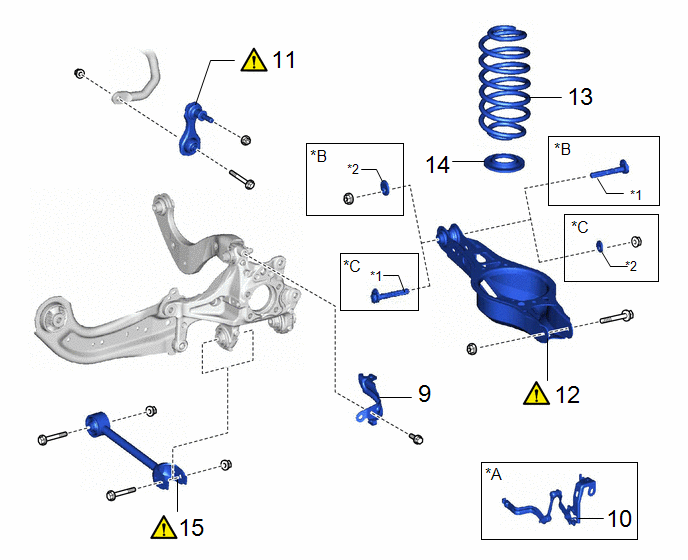
9 |
NO. 4 FLEXIBLE HOSE BRACKET |
47354B |
- |
- |
- |
|
10 |
REAR HEIGHT CONTROL SENSOR SUB-ASSEMBLY LH |
89408C |
- |
- |
- |
|
11 |
REAR STABILIZER LINK ASSEMBLY |
48840A |
|
- |
- |
|
12 |
REAR NO. 2 SUSPENSION ARM ASSEMBLY |
48740F |
|
- |
- |
|
13 |
REAR COIL SPRING |
48231B |
- |
- |
- |
|
14 |
REAR LOWER COIL SPRING INSULATOR |
48258C |
- |
- |
- |
|
15 |
REAR NO. 1 SUSPENSION ARM ASSEMBLY |
48720A |
|
- |
- |
|
*A |
for LH Side |
*B |
for Gasoline Model |
|
*C |
for HEV Model |
- |
- |
|
*1 |
REAR SUSPENSION TOE ADJUST CAM SUB-ASSEMBLY |
*2 |
NO. 2 CAMBER ADJUST CAM |
|
Procedure |
Part Name Code |
|
|
|
|
|---|---|---|---|---|---|
|
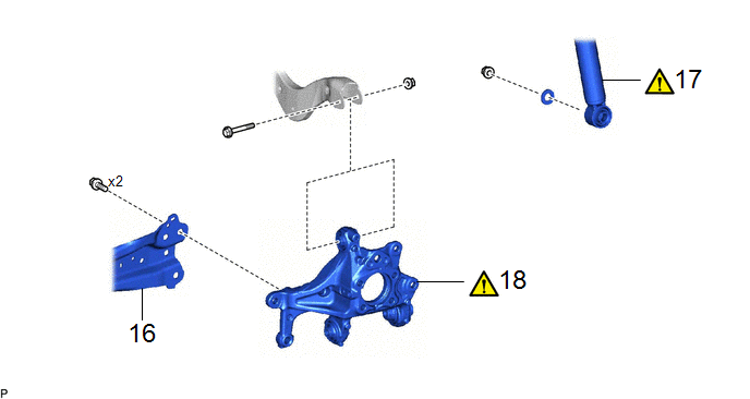
16 |
REAR TRAILING ARM ASSEMBLY |
48780E |
- |
- |
- |
|
17 |
REAR SHOCK ABSORBER ASSEMBLY |
- |
|
- |
- |
|
18 |
REAR AXLE CARRIER SUB-ASSEMBLY |
42305 |
|
- |
- |
CAUTION / NOTICE / HINT
The necessary procedures (adjustment, calibration, initialization, or registration) that must be performed after parts are removed and installed, or replaced during the rear axle carrier sub-assembly removal/installation are shown below.
Necessary Procedures After Procedure Performed|
Replaced Part or Performed Procedure |
Necessary Procedure |
Effect/Inoperative Function when Necessary Procedure not Performed |
Link |
|---|---|---|---|
|
Rear wheel alignment adjustment |
for HEV Model:
|
|
|
for Gasoline Model:
|
|
|
|
for Gasoline Model AWD:
|
Dynamic torque control AWD system |
|
|
|
Suspension, tires, etc. |
Rear television camera assembly optical axis (Back camera position setting) |
Parking Assist Monitor System |
|
|
Initialize headlight ECU subassembly LH |
Automatic headlight beam level control system |
|
HINT:
- Use the same procedure for the RH side and LH side.
- The following procedure is for the LH side.
PROCEDURE
1. REMOVE REAR WHEEL
Click here .gif)
2. REMOVE REAR SKID CONTROL SENSOR
|
|
Click here |
3. REMOVE REAR AXLE SHAFT NUT
|
|
|
4. DISCONNECT NO. 2 PARKING BRAKE WIRE ASSEMBLY
|
|
Click here |
5. SEPARATE REAR FLEXIBLE HOSE
Click here
6. SEPARATE REAR DISC BRAKE CALIPER ASSEMBLY
|
|
Click here |
7. REMOVE REAR DISC
|
|
Click here |
8. REMOVE REAR AXLE HUB AND BEARING ASSEMBLY
|
|
Click here |
9. REMOVE NO. 4 FLEXIBLE HOSE BRACKET

10. REMOVE REAR HEIGHT CONTROL SENSOR SUB-ASSEMBLY LH (w/ Height Control Sensor)
for LH Side:
Click here
11. REMOVE REAR STABILIZER LINK ASSEMBLY
|
|
Click here |
12. SEPARATE REAR NO. 2 SUSPENSION ARM ASSEMBLY
|
|
Click here |
13. REMOVE REAR COIL SPRING
Click here
14. REMOVE REAR LOWER COIL SPRING INSULATOR
Click here
15. REMOVE REAR NO. 1 SUSPENSION ARM ASSEMBLY
|
|
Click here |
16. LOOSEN REAR TRAILING ARM ASSEMBLY

17. LOOSEN REAR SHOCK ABSORBER ASSEMBLY
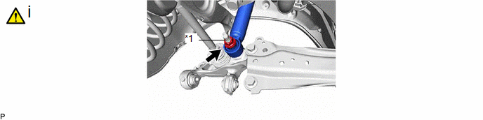
|
*1 |
Rear Axle Carrier Pin |
- |
- |
(1) Loosen the nut of the rear shock absorber assembly.
NOTICE:
Hold the rear axle carrier pin while rotating the nut.
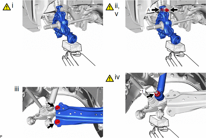
18. REMOVE REAR AXLE CARRIER SUB-ASSEMBLY
|
*1 |
Rear Axle Carrier Pin |
- |
- |
(1) Using a jack and a wooden block, support the rear axle carrier sub-assembly.
NOTICE:
- When jacking up the rear axle carrier sub-assembly, be sure to jack it up slowly.
- Make sure to perform this operation with the vehicle kept as low as possible.
(2) Loosen the bolt (A).
NOTICE:
Loosen the bolt with the nut secured.
(3) Remove the 2 bolts and separate the rear trailing arm assembly from the rear axle carrier sub-assembly.
(4) Remove the nut, plate washer and separate the rear shock absorber assembly from the rear axle carrier sub-assembly.
NOTICE:
Hold the rear axle carrier pin while rotating the nut.
(5) Remove the bolt (A), nut and rear axle carrier sub-assembly from the rear upper control arm assembly.
NOTICE:
- Loosen the bolt with the nut secured.
- Use wire or an equivalent tool to keep the rear drive shaft assembly from hanging by the rear differential carrier assembly.


