Toyota Corolla Cross: Reassembly
REASSEMBLY
CAUTION / NOTICE / HINT
COMPONENTS (REASSEMBLY)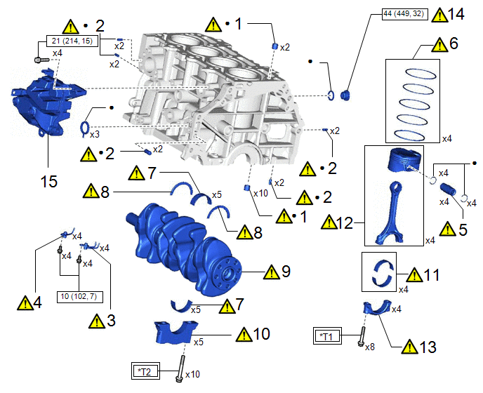
|
Procedure | Part Name Code |
.png) |
.png) |
 |
|---|---|---|---|---|---|
|
1 | RING PIN |
11115A |
|
- | - |
|
2 | STRAIGHT PIN |
11114A |
|
- | - |
|
3 | NO. 2 OIL NOZZLE SUB-ASSEMBLY |
15709 |
|
- | - |
|
4 | NO. 1 OIL NOZZLE SUB-ASSEMBLY |
15708 |
|
- | - |
|
5 | PISTON PIN |
- |
|
- | - |
|
6 | PISTON RING SET |
13011 |
|
- | - |
|
7 | CRANKSHAFT BEARING |
- |
|
- | - |
|
8 | CRANKSHAFT THRUST WASHER |
11791 |
|
- | - |
|
9 | CRANKSHAFT |
13411 |
|
- | - |
|
10 | CRANKSHAFT BEARING CAP |
- |
|
- | - |
|
11 | CONNECTING ROD BEARING |
- |
|
- | - |
|
12 | PISTON WITH CONNECTING ROD |
- |
|
- | - |
|
13 | CONNECTING ROD BEARING CAP |
- |
|
- | - |
|
14 | CYLINDER BLOCK WITH HEAD STRAIGHT SCREW PLUG |
11432R |
|
- | - |
|
15 | NO. 1 VENTILATION CASE |
12211 | - |
- | - |
.png) |
N*m (kgf*cm, ft.*lbf): Specified torque |
● | Non-reusable part |
|
*T1 | 38 N*m (387 kgf*cm, 28 ft.*lbf) |
*T2 | 61 N*m (622 kgf*cm, 45 ft.*lbf) |
PROCEDURE
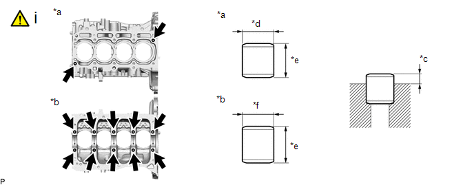
1. INSTALL RING PIN
|
*a | Top Side |
*b | Bottom Side |
|
*c | Protrusion Height |
*d | 13 mm (0.512 in.) |
|
*e | 12 mm (0.472 in.) |
*f | 14 mm (0.551 in.) |
(1) Using a plastic hammer, install 12 new ring pins.
Standard Protrusion Height:
5.0 to 7.0 mm (0.197 to 0.276 in.)
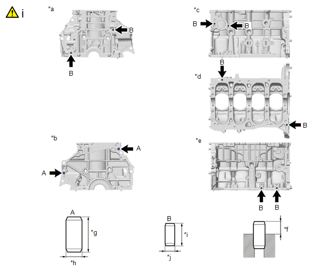
2. INSTALL STRAIGHT PIN
|
*a | Front Side |
*b | Rear Side |
|
*c | LH Side |
*d | Bottom Side |
|
*e | RH Side |
*f | Protrusion Height |
|
*g | 22 mm (0.866 in.) |
*h | 10 mm (0.394 in.) |
|
*i | 14 mm (0.551 in.) |
*j | 6.0 mm (0.236 in.) |
(1) Using a plastic hammer, tap in new straight pins to the cylinder block sub-assembly.
Standard Protrusion Height:
|
Straight Pin | Specified Condition |
|---|---|
|
(A) | 11.0 to 13.0 mm (0.433 to 0.512 in.) |
|
(B) | 5.0 to 7.0 mm (0.197 to 0.276 in.) |
3. INSTALL NO. 2 OIL NOZZLE SUB-ASSEMBLY
(1) Using a 5 mm hexagon wrench, install the 4 No. 2 oil nozzle sub-assemblies to the cylinder block sub-assembly with the 4 bolts.
Torque:
10 N·m {102 kgf·cm, 7 ft·lbf}
4. INSTALL NO. 1 OIL NOZZLE SUB-ASSEMBLY
(1) Using a 5 mm hexagon wrench, install the 4 No. 1 oil nozzle sub-assemblies to the cylinder block sub-assembly with the 4 bolts.
Torque:
10 N·m {102 kgf·cm, 7 ft·lbf}
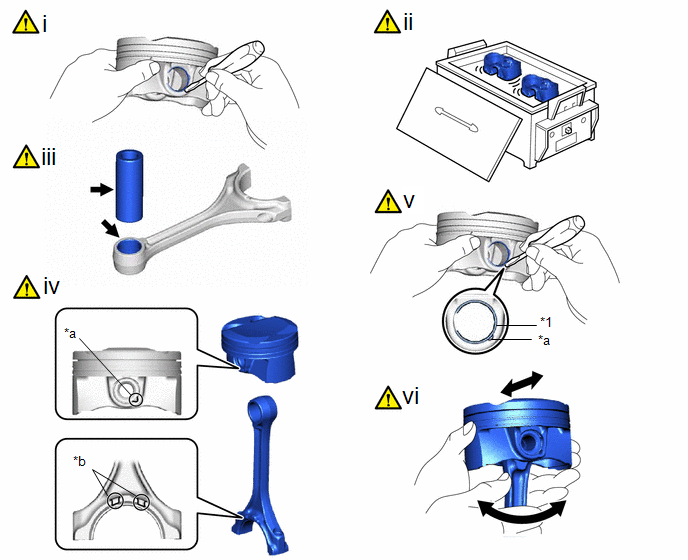
5. INSTALL PISTON PIN
|
*1 | Piston Pin Hole Snap Ring |
- | - |
|
*a | Cutout |
*b | Front Mark |
(1) Using a screwdriver, install a new piston pin hole snap ring (rear side) at one end of the piston pin hole.
(2) Gradually heat the piston to approximately 80 to 90°C (176 to 194°F).
CAUTION:
Be sure to wear protective gloves.
(3) Apply a light coat of engine oil to the piston, piston pin and connecting rod.
(4) Align the front marks of the piston and connecting rod, insert the connecting rod into the piston, and then push in the piston pin with your thumb until the piston pin comes into contact with the snap ring.
HINT:
The piston and piston pin are a matched set.
(5) Using a screwdriver, install a new piston pin hole snap ring at the other end of the piston pin hole.
NOTICE:
Make sure that the end gap of the snap ring is not aligned with the cutout of the piston pin hole.
(6) Check the fitting condition between the piston and piston pin by trying to move the piston back and forth on the piston pin.
HINT:
Perform "Inspection After Repair" after replacing the piston.
Click here .gif)
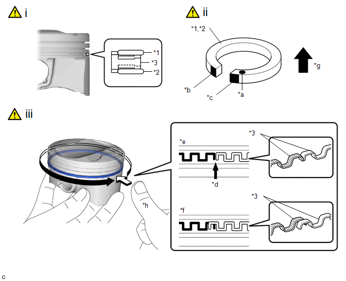
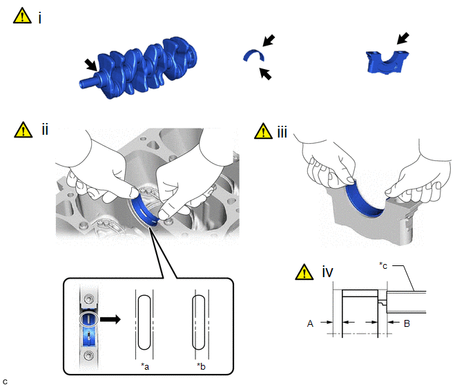
6. INSTALL PISTON RING SET
|
*1 | Upper Side Rail |
*2 | Lower Side Rail |
|
*3 | Oil Ring Expander |
- | - |
|
*a | Code Mark (T) |
*b | Paint (Orange) |
|
*c | Paint (Light Green) |
*d | Ring End |
|
*e | Correct |
*f | Incorrect (Ends of the oil ring expander are overlapping) |
|
*g | Upper Side |
*h | Press around the circumference |
(1) Install the oil ring expander, upper side rail and lower side rail to the piston by hand.
(2) Install the upper side rail and lower side rail to the piston.
NOTICE:
When installing the upper side rail and lower side rail, the ends of the oil ring expander may overlap. If it occurs, the upper side rail or lower side rail may move out of its groove.
(3) Check that the ends of the oil ring expander are not overlapping and that the upper side rail and lower side rail are securely installed into the groove.
NOTICE:
- After installing the oil ring expander, upper side rail and lower side rail, press around the circumference with a finger to check that they are securely installed into the groove.
- If the oil ring expander is not securely installed into the groove, check that the ends of the oil ring expander are not overlapping.
- If the ends of the oil ring expander are overlapping, remove the upper side rail and lower side rail and realign the oil ring expander using a screwdriver.
|
*1 | No. 1 Compression Ring |
*2 | No. 2 Compression Ring |
|
*a | Code Mark |
*b | Paint Mark |
|
*c | Front Mark |
*d | No. 1 Compression Ring |
|
*e | No. 2 Compression Ring |
*f | Oil Ring Expander |
|
*g | Lower Side Rail |
*h | Lower Side Rail |
.png) |
Upward |
 |
Front of Engine |
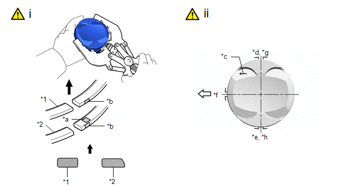
(1) Using a piston ring expander, install the No. 1 compression ring and No. 2 compression ring so that the paint marks are positioned as shown in the illustration.
Piston Ring Mark:
|
Item | Code Mark |
Paint Mark |
|---|---|---|
| No. 1 Compression Ring |
- | White |
|
No. 2 Compression Ring |
2T | Sky Blue |
NOTICE:
Install the No. 2 compression ring with the code mark (2T) facing upward.
(2) Position the piston ring set so that the ring ends are as shown in the illustration.
HINT:
Perform "Inspection After Repair" after replacing the piston ring.
Click here
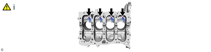
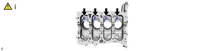
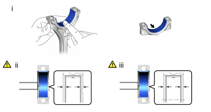
7. INSTALL CRANKSHAFT BEARING
|
*a | Correct |
*b | Incorrect |
|
*c | Vernier Caliper |
- | - |
(1) Clean the main journal and both surfaces of the No. 1 crankshaft bearings and No. 2 crankshaft bearings.
(2) Install the 5 No. 1 crankshaft bearings to the cylinder block sub-assembly as shown in the illustration.
NOTICE:
Do not apply engine oil to the No. 1 crankshaft bearings or the contact surfaces.
HINT:
Both sides of the oil groove in the cylinder block sub-assembly should be visible through the oil feed holes in the No. 1 crankshaft bearing. The amount visible on each side of the holes should be equal.
(3) Install the 5 No. 2 crankshaft bearings to the 5 crankshaft bearing caps.
NOTICE:
Do not apply engine oil to the No. 2 crankshaft bearings or the contact surfaces.
(4) Using a vernier caliper, measure the distance between the crankshaft bearing cap edge and No. 2 crankshaft bearing edge.
Difference between (A) and (B):
0 to 0.7 mm (0 to 0.0276 in.)
8. INSTALL CRANKSHAFT THRUST WASHER
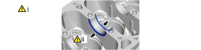
(1) Install the 2 crankshaft thrust washers to the No. 3 journal position of the cylinder block sub-assembly with the oil grooves facing outward.
(2) Apply engine oil to the crankshaft thrust washers.
9. INSTALL CRANKSHAFT
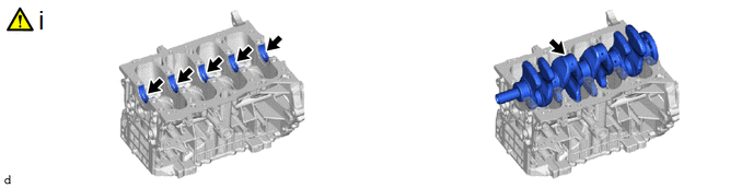
(1) Apply engine oil to the upper crankshaft bearings and install the crankshaft to the cylinder block sub-assembly.
10. INSTALL CRANKSHAFT BEARING CAP
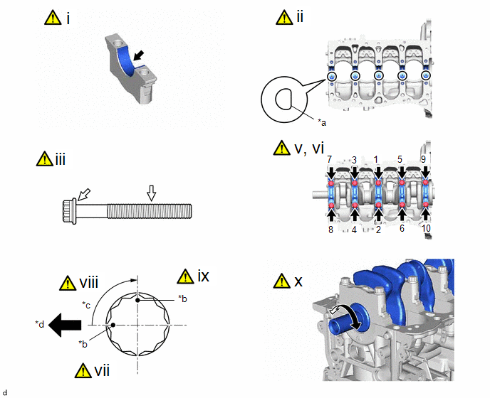
|
*a | Front Mark |
*b | Paint Mark |
|
*c | 90° |
*d | Front of Engine |
(1) Apply engine oil to the lower crankshaft bearings.
(2) Confirm the front marks and numbers, and place the 5 crankshaft bearing caps on the cylinder block sub-assembly.
(3) Apply a light coat of engine oil to the threads and under the heads of the crankshaft bearing cap set bolts.
(4) Using a plastic hammer, lightly tap the crankshaft bearing caps to ensure a proper fit.
(5) Install the crankshaft bearing cap set bolts.
NOTICE:
The crankshaft bearing cap set bolts are tightened in 2 progressive steps.
(6) Uniformly tighten the 10 crankshaft bearing cap set bolts.
Torque:
61 N·m {622 kgf·cm, 45 ft·lbf}
HINT:
If a crankshaft bearing cap set bolt cannot be tightened to the specified torque, replace it.
(7) Mark the front of the crankshaft bearing cap set bolts with paint.
(8) Tighten the 10 crankshaft bearing cap set bolts 90° as shown in the illustration.
(9) Check that the paint marks are now at a 90° angle to the front.
(10) Check that the crankshaft turns smoothly.
11. INSTALL CONNECTING ROD BEARING
(1) Clean the connecting rod bearing contact surfaces of the connecting rod and connecting rod cap, and both surfaces of the 2 connecting rod bearings.
(2) Install the 8 connecting rod bearings to the 4 connecting rods and 4 connecting rod caps.
(3) Using a vernier caliper, measure the distance between the edges of the connecting rod and connecting rod bearing, and the edges of the connecting rod cap and connecting rod bearing.
Difference between (A) and (B):
0 to 0.7 mm (0 to 0.0276 in.)
NOTICE:
Do not apply engine oil to the connecting rod bearings or the contact surfaces.
12. INSTALL PISTON WITH CONNECTING ROD
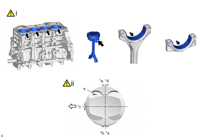
|
*a | No. 1 Compression Ring |
*b | No. 2 Compression Ring |
|
*c | Oil Ring Expander |
*d | Upper Side Rail |
|
*e | Lower Side Rail |
*f | Front Mark |
|
|
Front of Engine | - |
- |
(1) Apply engine oil to the cylinder walls, pistons, and surfaces of the connecting rod bearings.
(2) Position the piston rings so that the ring ends are as shown in the illustration.
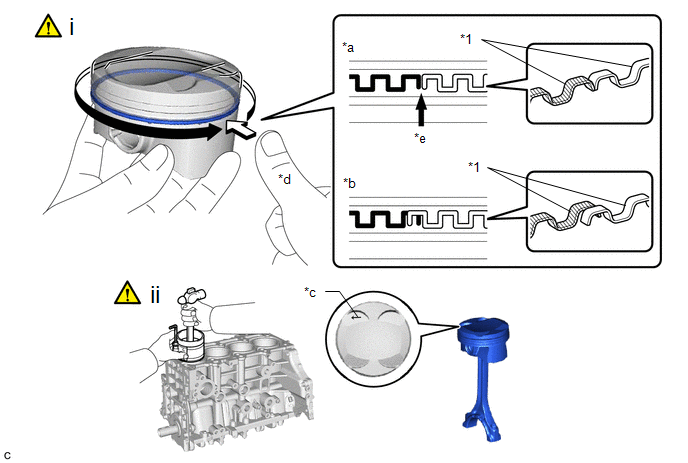
|
*1 | Oil Ring Expander |
- | - |
|
*a | Correct |
*b | Incorrect (Ends of the oil ring expander are overlapping) |
|
*c | Front Mark |
*d | Press around the circumference |
|
*e | Ring End |
- | - |
(1) Confirm that the ends of the oil ring expander are not overlapping and that the upper side rail and lower side rail are securely installed into the groove.
NOTICE:
- After installing the oil ring expander, upper side rail and lower side rail, press around the circumference with a finger to check that they are securely installed into the groove.
- If the oil ring expander is not securely installed into the groove, check that the ends of the oil ring expander are not overlapping.
- If the ends of the oil ring expander are overlapping, remove the upper side rail and lower side rail and realign the oil ring expander.
(2) Using a piston ring compressor, push the correctly numbered piston with connecting rod into the cylinder with the front marks of each piston with connecting rod facing the front of the engine.
NOTICE:
- When inserting the piston with connecting rod into the cylinder block sub-assembly, make sure the connecting rod does not contact the No. 1 oil nozzle sub-assembly.
- Match each connecting rod cap to the correct connecting rod.
13. INSTALL CONNECTING ROD BEARING CAP
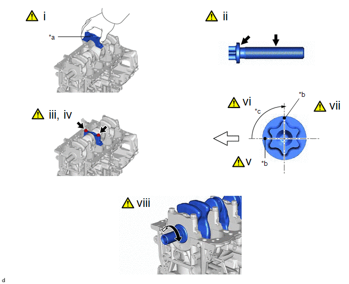
|
*a | Front Mark |
*b | Paint Mark |
|
*c | 90° |
- | - |
|
|
Front of Engine | - |
- |
(1) Check that the front mark of the connecting rod cap is facing the correct direction.
(2) Apply a light coat of engine oil to the threads and under the heads of the connecting rod bolts.
(3) Install the 8 connecting rod bolts.
NOTICE:
The connecting rod bolts are tightened in 2 progressive steps.
(4) Using an E12 "TORX" socket wrench, alternately tighten the 2 connecting rod bolts in several steps.
Torque:
38 N·m {387 kgf·cm, 28 ft·lbf}
(5) Mark the front of the connecting rod bolts with paint.
(6) Tighten the connecting rod bolts 90° as shown in the illustration.
(7) Check that the paint marks are now at a 90° angle to the front.
(8) Check that the crankshaft turns smoothly.
14. INSTALL CYLINDER BLOCK WITH HEAD STRAIGHT SCREW PLUG
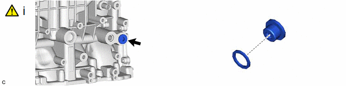
(1) Using a 10 mm hexagon wrench, install the cylinder block with head straight screw plug and a new gasket to the cylinder block sub-assembly.
Torque:
44 N·m {449 kgf·cm, 32 ft·lbf}
15. INSTALL NO. 1 VENTILATION CASE
Torque:
21 N·m {214 kgf·cm, 15 ft·lbf}


