Toyota Corolla Cross: Power Window Master Switch
Removal
REMOVAL
CAUTION / NOTICE / HINT
COMPONENTS (REMOVAL)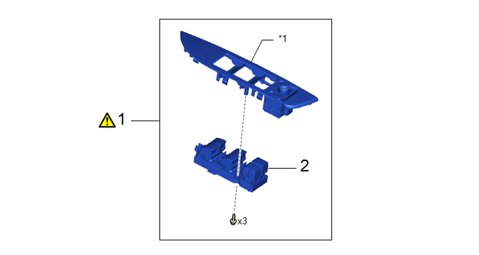
|
Procedure | Part Name Code |
.png) |
.png) |
 |
|---|---|---|---|---|---|
|
1 | MULTIPLEX NETWORK MASTER SWITCH ASSEMBLY WITH FRONT DOOR UPPER ARMREST BASE PANEL |
- |
|
- | - |
|
2 | MULTIPLEX NETWORK MASTER SWITCH ASSEMBLY |
84040 | - |
- | - |
.gif)
|
*1 | FRONT DOOR UPPER ARMREST BASE PANEL |
- | - |
PROCEDURE
1. REMOVE MULTIPLEX NETWORK MASTER SWITCH ASSEMBLY WITH FRONT DOOR UPPER ARMREST BASE PANEL
|
|
Click here |
2. REMOVE MULTIPLEX NETWORK MASTER SWITCH ASSEMBLY

Inspection
INSPECTION
PROCEDURE
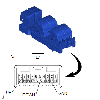
1. INSPECT MULTIPLEX NETWORK MASTER SWITCH ASSEMBLY
(a) Check the resistance.
| (1) Measure the resistance according to the value(s) in the table below. Standard Resistance:
If the result is not as specified, replace the multiplex network master switch assembly. |
|
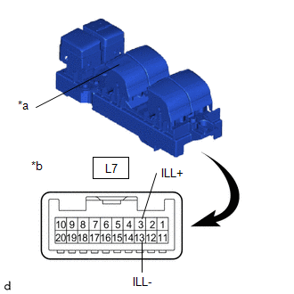
(b) Check that the LED illuminate.
| (1) Apply auxiliary battery voltage to the multiplex network master switch assembly and check that the LED illuminates. OK:
If the result is not as specified, replace the multiplex network master switch assembly. |
|
Installation
INSTALLATION
CAUTION / NOTICE / HINT
COMPONENTS (INSTALLATION)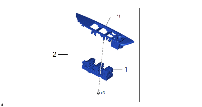
|
Procedure | Part Name Code |
.png) |
.png) |
 |
|---|---|---|---|---|---|
|
1 | MULTIPLEX NETWORK MASTER SWITCH ASSEMBLY |
84040 | - |
- | - |
|
2 | MULTIPLEX NETWORK MASTER SWITCH ASSEMBLY WITH FRONT DOOR UPPER ARMREST BASE PANEL |
- | - |
- | - |
|
*1 | FRONT DOOR UPPER ARMREST BASE PANEL |
- | - |
PROCEDURE
1. INSTALL MULTIPLEX NETWORK MASTER SWITCH ASSEMBLY
2. INSTALL MULTIPLEX NETWORK MASTER SWITCH ASSEMBLY WITH FRONT DOOR UPPER ARMREST BASE PANEL


