Toyota Corolla Cross: Hybrid Battery Stack 2 Cell Voltage Detection Voltage Out of Range (P1A001C,P301A1C)
DESCRIPTION
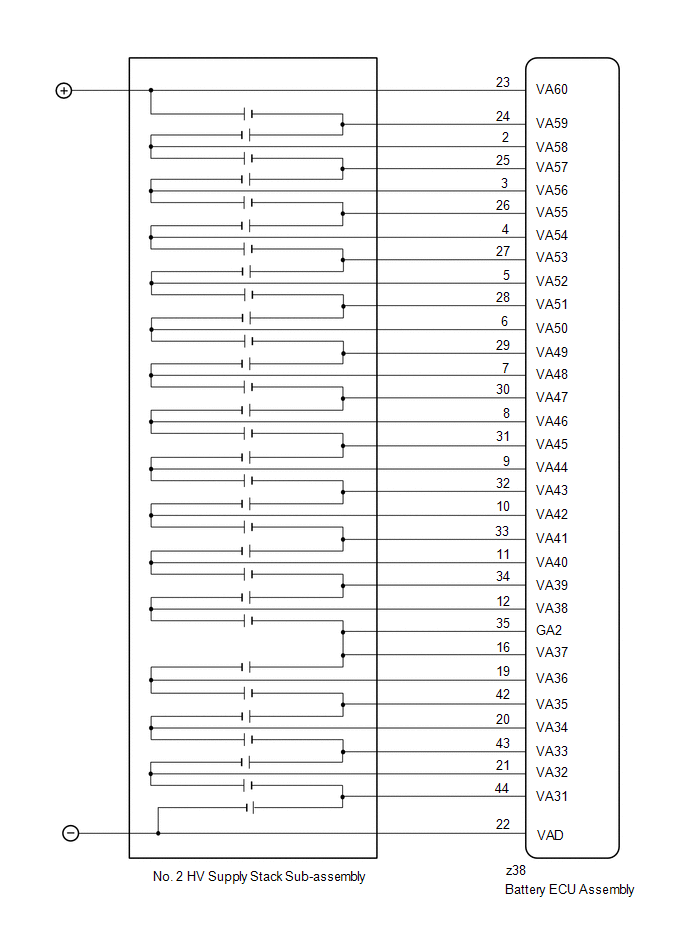
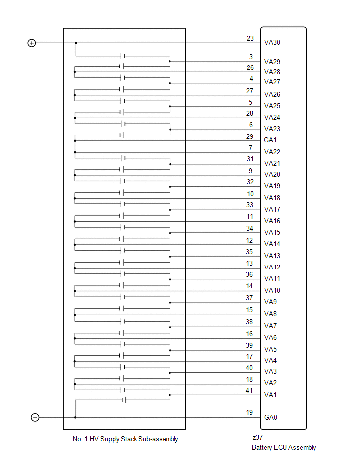
The HV battery is composed of 60 cells (3.7 V each) in series. The battery ECU assembly monitors the voltage of each HV battery cell to detect malfunctions of the HV battery.
|
DTC No. | Detection Item |
DTC Detection Condition |
Trouble Area | MIL |
Warning Indicate | Note |
|---|---|---|---|---|---|---|
|
P1A001C | Hybrid Battery Stack 2 Cell Voltage Detection Voltage Out of Range |
An open is detected in the HV battery cell voltage detection circuits of the No. 2 HV supply stack sub-assembly. (1 trip detection logic) |
| Comes on |
Master Warning: Comes on |
SAE Code: P1A00 |
|
P301A1C | Hybrid Battery Stack 1 Cell Voltage Detection Voltage Out of Range |
An open is detected in the HV battery cell voltage detection circuits of the No. 1 HV supply stack sub-assembly. (1 trip detection logic) |
| Comes on |
Master Warning: Comes on |
SAE Code: P301A |
MONITOR DESCRIPTION
If the voltage of an HV battery cell is abnormal, the battery ECU assembly will determine that a malfunction has occurred. When the malfunction detection condition is satisfied, the battery ECU assembly will illuminate the MIL and store a DTC.
MONITOR STRATEGY
|
Related DTCs | P1A00 (INF P1A001C), P301A (INF P301A1C): Battery voltage detection circuits malfunction |
|
Required sensors/components | Battery ECU assembly |
|
Frequency of operation | Continuous |
|
Duration | TMC's intellectual property |
|
MIL operation | Immediately |
|
Sequence of operation | None |
TYPICAL ENABLING CONDITIONS
|
The monitor will run whenever the following DTCs are not stored |
TMC's intellectual property |
|
Other conditions belong to TMC's intellectual property |
- |
TYPICAL MALFUNCTION THRESHOLDS
|
TMC's intellectual property | - |
COMPONENT OPERATING RANGE
|
Battery ECU assembly | DTC P1A00 (INF P1A001C) is not detected DTC P301A (INF P301A1C) is not detected |
CONFIRMATION DRIVING PATTERN
HINT:
- After repair has been completed, clear the DTC and then check that the vehicle has returned to normal by performing the following All Readiness check procedure.
Click here
.gif)
- When clearing the permanent DTCs, refer to the "CLEAR PERMANENT DTC" procedure.
Click here
- Connect the GTS to the DLC3.
- Turn the ignition switch to ON and turn the GTS on.
- Clear the DTCs (even if no DTCs are stored, perform the clear DTC procedure).
- Turn the ignition switch off and wait for 2 minutes or more.
- Turn the ignition switch to ON and turn the GTS on.
- With ignition switch ON and wait for 10 seconds or more.[*1]
HINT:
[*1]: Normal judgment procedure.
The normal judgment procedure is used to complete DTC judgment and also used when clearing permanent DTCs.
- Enter the following menus: Powertrain / HV Battery / Utility / All Readiness.
- Check the DTC judgment result.
HINT:
- If the judgment result shows NORMAL, the system is normal.
- If the judgment result shows ABNORMAL, the system has a malfunction.
- If the judgment result shows INCOMPLETE, perform the normal judgment procedure again.
WIRING DIAGRAM
CAUTION / NOTICE / HINT
CAUTION:
Refer to the precautions before inspecting high voltage circuit.
Click here
NOTICE:
- After the ignition switch is turned off, there may be a waiting time before disconnecting the negative (-) auxiliary battery terminal.
Click here
- When disconnecting and reconnecting the auxiliary battery
HINT:
When disconnecting and reconnecting the auxiliary battery, there is an automatic learning function that completes learning when the respective system is used.
Click here
PROCEDURE
|
1. | CHECK DTC OUTPUT (HV BATTERY, HYBRID CONTROL) |
(a) Check for DTCs.
Powertrain > HV Battery > Trouble Codes Powertrain > Hybrid Control > Trouble Codes|
Result | Proceed to |
|---|---|
|
"P1A001C or P301A1C" only is output, or DTCs except the ones in the table below are also output. |
A |
| DTCs of hybrid battery system in the table below are output. |
B |
| DTCs of hybrid control system in the table below are output. |
C |
|
System | Relevant DTC | |
|---|---|---|
|
Hybrid battery system |
P060A47 | Hybrid/EV Battery Energy Control Module Monitoring Processor Watchdog / Safety MCU Failure |
|
P060B49 | Hybrid/EV Battery Energy Control Module A/D Processing Internal Electronic Failure | |
|
P060687 | Hybrid/EV Battery Energy Control Module Processor to Monitoring Processor Missing Message | |
|
Hybrid control system |
P0A1F94 | Hybrid/EV Battery Energy Control Module Unexpected Operation |
(b) Turn the ignition switch off.
| B | .gif) | GO TO DTC CHART (HYBRID BATTERY SYSTEM) |
| C | | GO TO DTC CHART (HYBRID CONTROL SYSTEM) |
|
.gif)
|
2. | CHECK DTC |
(a) Check the DTCs that were output when the vehicle was brought to the workshop.
|
Result | Proceed to |
|---|---|
|
"P1A001C" is also output. |
A |
| "P301A1C" is also output. |
B |
| B | | GO TO STEP 6 |
|
|
3. | CHECK CONNECTOR CONNECTION CONDITION (BATTERY ECU ASSEMBLY CONNECTOR) |
CAUTION:
Be sure to wear insulated gloves and protective goggles.
(a) Check that the service plug grip is not installed.
NOTICE:
After removing the service plug grip, do not turn the ignition switch to ON (READY), unless instructed by the repair manual because this may cause a malfunction.
| (b) Check the connector connections and contact pressure of the relevant terminals for the battery ECU assembly. Click here OK: The connector is connected securely and there are no contact problems. Result:
|
| |||||||||||||
.png)
| B | | CONNECT SECURELY |
| C | | REPLACE HV BATTERY |
|
|
4. | CHECK FREEZE FRAME DATA (HYBRID/EV BATTERY CELL VOLTAGE) |
(a) Read the value of freeze frame data items "Hybrid/EV Battery Cell 31 Voltage" through "Hybrid/EV Battery Cell 60 Voltage" for DTC P1A001C and make a note if the value of any is 1.6 V or less.
Powertrain > HV Battery > Trouble Codes(b) Turn the ignition switch off.
|
|
5. | CHECK HV BATTERY (HV BATTERY CELL VOLTAGE 31 - 60) |
Click here
| Result |
Proceed to |
|---|---|
| The voltage between the terminals is 1.6 V or less. |
A |
| Other than above |
B |
| A | | REPLACE HV BATTERY |
| B | | REPLACE BATTERY ECU ASSEMBLY |
|
6. | CHECK CONNECTOR CONNECTION CONDITION (BATTERY ECU ASSEMBLY CONNECTOR) |
CAUTION:
Be sure to wear insulated gloves and protective goggles.
(a) Check that the service plug grip is not installed.
NOTICE:
After removing the service plug grip, do not turn the ignition switch to ON (READY), unless instructed by the repair manual because this may cause a malfunction.
| (b) Check the connector connections and contact pressure of the relevant terminals for the battery ECU assembly. Click here OK: The connector is connected securely and there are no contact problems. Result:
|
| |||||||||||||
.png)
| B | | CONNECT SECURELY |
| C | | REPLACE HV BATTERY |
|
|
7. | CHECK FREEZE FRAME DATA (HYBRID/EV BATTERY CELL VOLTAGE) |
(a) Read the value of freeze frame data items "Hybrid/EV Battery Cell 1 Voltage" through "Hybrid/EV Battery Cell 30 Voltage" for DTC P301A1C and make a note if the value of any is 1.6 V or less.
Powertrain > HV Battery > Trouble Codes(b) Turn the ignition switch off.
|
|
8. | CHECK HV BATTERY (HV BATTERY CELL VOLTAGE 1 - 30) |
Click here
| Result |
Proceed to |
|---|---|
| The voltage between the terminals is 1.6 V or less. |
A |
| Other than above |
B |
| A | | REPLACE HV BATTERY |
| B | | REPLACE BATTERY ECU ASSEMBLY |
READ NEXT:
 Hybrid/EV Battery Stack 2 Cell Circuit Voltage Above Threshold (P1A6017,P31AA17)
DESCRIPTION The HV battery is composed of 60 cells (3.7 V each) in series. The battery ECU assembly monitors the voltage of each HV battery cell to detect malfunctions of the HV battery.
DTC No
Hybrid/EV Battery Stack 2 Cell Circuit Voltage Below Threshold (P1A6116,P31AB16)
DESCRIPTION If the voltage of an HV battery cell is lower than the threshold for a certain amount of time, the battery ECU assembly will interpret this as a malfunction.
DTC No. Detection Ite
Hybrid/EV Battery Stack 1 Delta SOC High (P1A8000,P1A8500)
DESCRIPTION The HV battery is composed of 60 cells (3.7 V each) in series. The battery ECU assembly monitors the difference in capacity of each HV battery cell to detect malfunctions of the HV battery
SEE MORE:
 A/F (O2) Sensor Signal Biased/Stuck Lean Bank 1 Sensor 2 Circuit Current Above Threshold (P227019,P227118)
DESCRIPTION Refer to DTC P003612. Click here
HINT: Although the DTC title say O2 sensor, these DTCs relate to the air fuel ratio sensor (sensor 2).
DTC No. Detection Item
DTC Detection Condition Trouble Area
MIL Note
P227019 A/F (O2) Sensor Signal Biased/Stuck Lea
Diagnostic Trouble Code Chart
DIAGNOSTIC TROUBLE CODE CHART Hybrid Control System
DTC No. Detection Item
MIL Warning Indicate
Note Link
C134800 Different Diameter Tire
Does not come on Master Warning:
Does not come on SAE Code:
C1348
P05042B Brake Swit
