Toyota Corolla Cross: Parts Location
PARTS LOCATION
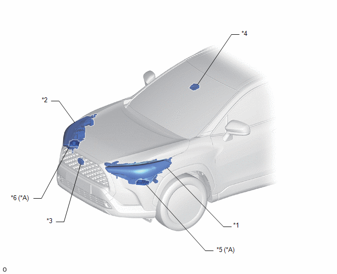
ILLUSTRATION
|
*A |
w/ AFS |
- |
- |
|
*1 |
HEADLIGHT ASSEMBLY LH |
*2 |
HEADLIGHT ASSEMBLY RH |
|
*3 |
MILLIMETER WAVE RADAR SENSOR ASSEMBLY |
*4 |
FORWARD RECOGNITION CAMERA |
|
*5 |
HEADLIGHT ECU SUB-ASSEMBLY LH |
*6 |
HEADLIGHT ECU SUB-ASSEMBLY RH |
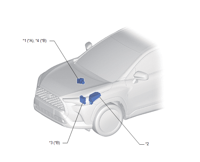
ILLUSTRATION
|
*A |
for HEV Model |
*B |
for Gasoline Model |
|
*1 |
SKID CONTROL ECU (BRAKE ACTUATOR ASSEMBLY) |
*2 |
NO. 1 ENGINE ROOM RELAY BLOCK - H-LP RH RELAY - H-LP LH RELAY |
|
*3 |
ECM |
*4 |
SKID CONTROL ECU (BRAKE ACTUATOR ASSEMBLY) |
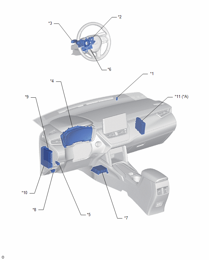
ILLUSTRATION
|
*A |
for HEV Model |
- |
- |
|
*1 |
AUTOMATIC LIGHT CONTROL SENSOR |
*2 |
STEERING WHEEL SWITCH HOUSING |
|
*3 |
TURN SIGNAL SWITCH |
*4 |
COMBINATION METER ASSEMBLY |
|
*5 |
AUTO HIGH BEAM SWITCH |
*6 |
STEERING SENSOR |
|
*7 |
AIRBAG ECU ASSEMBLY |
*8 |
DLC3 |
|
*9 |
MAIN BODY ECU (MULTIPLEX NETWORK BODY ECU) |
*10 |
POWER DISTRIBUTION BOX ASSEMBLY - ECU-B NO.2 FUSE |
|
*11 |
HYBRID VEHICLE CONTROL ECU |
- |
- |


