Toyota Corolla Cross: Operating Light Control Rheostat does not Change Light Brightness
DESCRIPTION
The combination meter assembly receives signals from this circuit to adjust the illumination of the combination meter assembly. The combination meter assembly sets the illumination level based on the user operation of the light control rheostat switch.
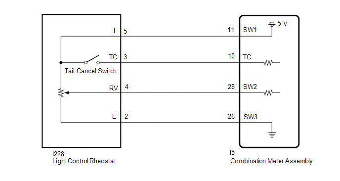
WIRING DIAGRAM
CAUTION / NOTICE / HINT
NOTICE:
- When replacing the combination meter assembly, always replace it with a new one. If a combination meter assembly which was installed to another vehicle is used, the information stored in it will not match the information from the vehicle and a DTC may be stored.
- When replacing the combination meter assembly, update the ECU security key.
Click here
.gif)
HINT:
- The meter illumination level can be adjusted by pressing the light control rheostat switch.
- The meter illumination dims when the taillights are turned on.
- Setting the meter illumination level to maximum brightness cancels the above dimming of the meter illumination.
PROCEDURE
|
1. | READ VALUE USING GTS |
(a) Using the GTS, read the Data List.
Click here
|
Tester Display | Measurement Item |
Range | Normal Condition |
Diagnostic Note |
|---|---|---|---|---|
|
Meter Day Mode Switch | Light control rheostat (tail cancel switch) signal |
OFF or ON | OFF: Light control rheostat (tail cancel switch) off ON: Light control rheostat (tail cancel switch) on |
- |
| Rheostat value |
Light control rheostat input signal |
Min.: 0.00%, Max.: 100.02% or Unset |
Light control rheostat dark (0.00%) → bright (100.02%) |
- |
|
Tester Display |
|---|
| Meter Day Mode Switch |
|
Rheostat value |
OK:
Light control rheostat condition displayed on the GTS changes with the actual switch operation.
| OK | .gif) | REPLACE COMBINATION METER ASSEMBLY |
|
.gif)
| 2. |
INSPECT LIGHT CONTROL RHEOSTAT |
Click here
| NG | |
REPLACE LIGHT CONTROL RHEOSTAT |
|
| 3. |
CHECK HARNESS AND CONNECTOR (COMBINATION METER ASSEMBLY - LIGHT CONTROL RHEOSTAT) |
(a) Disconnect the I5 combination meter assembly connector.
(b) Disconnect the I228 light control rheostat connector.
(c) Measure the resistance according to the value(s) in the table below.
Standard Resistance:
|
Tester Connection | Condition |
Specified Condition |
|---|---|---|
|
I5-11 (SW1) - I228-5 (T) |
Always | Below 1 Ω |
|
I5-10 (TC) - I228-3 (TC) |
Always | Below 1 Ω |
|
I5-28 (SW2) - I228-4 (RV) |
Always | Below 1 Ω |
|
I5-26 (SW3) - I228-2 (E) |
Always | Below 1 Ω |
|
I5-11 (SW1) or I228-5 (T) - Body ground |
Always | 10 kΩ or higher |
|
I5-10 (TC) or I228-3 (TC) - Body ground |
Always | 10 kΩ or higher |
|
I5-28 (SW2) or I228-4 (RV) - Body ground |
Always | 10 kΩ or higher |
|
I5-26 (SW3) or I228-2 (E) - Body ground |
Always | 10 kΩ or higher |
| OK | | REPLACE COMBINATION METER ASSEMBLY |
| NG | | REPAIR OR REPLACE HARNESS OR CONNECTOR |


