Toyota Corolla Cross: Steering Pad Switch Circuit
DESCRIPTION
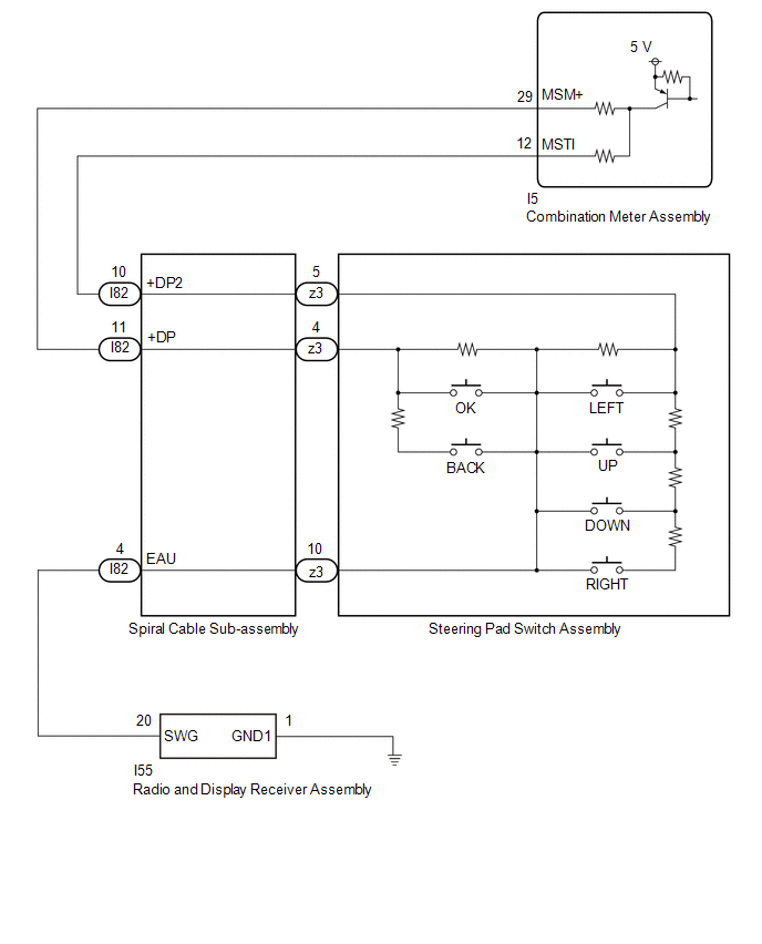
The combination meter assembly and steering pad switch assembly are connected via direct line.
- The multi-information display in the combination meter assembly is operated using the switches of the steering pad switch assembly.
WIRING DIAGRAM
CAUTION / NOTICE / HINT
NOTICE:
When replacing the combination meter assembly, always replace it with a new one. If a combination meter assembly which was installed to another vehicle is used, the information stored in it will not match the information from the vehicle and a DTC may be stored.
- When replacing the combination meter assembly, always replace it with a new one. If a combination meter assembly which was installed to another vehicle is used, the information stored in it will not match the information from the vehicle and a DTC may be stored.
- When replacing the combination meter assembly, update the ECU security key.
Click here
.gif)
PROCEDURE
|
1. | INSPECT STEERING PAD SWITCH ASSEMBLY |
Click here
| NG | .gif) | REPLACE STEERING PAD SWITCH ASSEMBLY |
|
.gif)
| 2. |
INSPECT SPIRAL CABLE SUB-ASSEMBLY |
Click here
| NG | |
REPLACE SPIRAL CABLE SUB-ASSEMBLY |
|
| 3. |
CHECK COMBINATION METER ASSEMBLY (OUTPUT VOLTAGE) |
|
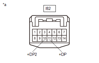
*a | Front view of wire harness connector (to Spiral Cable Sub-assembly) |
(a) Measure the voltage according to the value(s) in the table below.
Standard Voltage:
|
Tester Connection | Switch Condition |
Specified Condition |
|---|---|---|
|
I82-11 (+DP) - Body ground |
Ignition switch ON | 4.8 to 5.2 V |
|
I82-10 (+DP2) - Body ground |
Ignition switch ON | 4.8 to 5.2 V |
| NG | | GO TO STEP 5 |
|
| 4. |
CHECK HARNESS AND CONNECTOR (SPIRAL CABLE SUB-ASSEMBLY - BODY GROUND) |
(a) Disconnect the I55 radio and display receiver assembly connector.
(b) Measure the resistance according to the value(s) in the table below.
Standard Resistance:
|
Tester Connection | Condition |
Specified Condition |
|---|---|---|
|
I55-20 (SWG) - I82-4 (EAU) |
Always | Below 1 Ω |
|
I55-1 (GND1) - Body ground |
Always | Below 1 Ω |
| OK | | REPLACE RADIO AND RECEIVER ASSEMBLY |
| NG | | REPAIR OR REPLACE HARNESS OR CONNECTOR |
| 5. |
CHECK HARNESS AND CONNECTOR (SPIRAL CABLE SUB-ASSEMBLY - COMBINATION METER ASSEMBLY) |
(a) Disconnect the I5 combination meter assembly connector.
(b) Measure the resistance according to the value(s) in the table below.
Standard Resistance:
|
Tester Connection | Condition |
Specified Condition |
|---|---|---|
|
I82-11 (+DP) - I5-29 (MSM+) |
Always | Below 1 Ω |
|
I82-10 (+DP2) - I5-12 (MSTI) |
Always | Below 1 Ω |
|
I82-11 (+DP) or I5-29 (MSM+) - Body ground |
Always | 10 kΩ or higher |
|
I82-10 (+DP2) or I5-12 (MSTI) - Body ground |
Always | 10 kΩ or higher |
| OK | | REPLACE COMBINATION METER ASSEMBLY |
| NG | | REPAIR OR REPLACE HARNESS OR CONNECTOR |


