Toyota Corolla Cross: Manifold Absolute Pressure - Barometric Pressure Correlation (P006900)
DESCRIPTION
The E.F.I. vacuum sensor assembly installed to the intake manifold detects the intake manifold pressure using a built-in sensor.
An atmospheric pressure sensor is built into the ECM. When the engine is stopped, the value of the E.F.I. vacuum sensor assembly and atmospheric pressure sensor will be approximately the same as the atmospheric pressure.
|
DTC No. | Detection Item |
DTC Detection Condition | Trouble Area |
MIL | Note |
|---|---|---|---|---|---|
|
P006900 | Manifold Absolute Pressure - Barometric Pressure Correlation |
Difference between atmospheric pressure value of the absolute pressure sensor and atmospheric pressure sensor is higher than threshold value (2 trip detection logic). |
|
|
|
MONITOR DESCRIPTION
Approximately 50 minutes after the ignition switch is turned off, the soak timer is activated and the values of the E.F.I. vacuum sensor assembly and atmospheric pressure sensor are compared. If the difference between the values of the E.F.I. vacuum sensor assembly and atmospheric pressure sensor is higher than a threshold value in consecutive driving cycles, the ECM will store this DTC.
MONITOR STRATEGY
|
Related DTCs | P0069: E.F.I. vacuum sensor assembly/Atmospheric pressure sensor correlation |
|
Required Sensors/Components (Main) | E.F.I. vacuum sensor assembly ECM |
| Required Sensors/Components (Related) |
Mass air flow meter sub-assembly Engine coolant temperature sensor |
|
Frequency of Operation | Once per driving cycle |
|
Duration | 3 times |
|
MIL Operation | 2 driving cycles |
|
Sequence of Operation | None |
TYPICAL ENABLING CONDITIONS
|
All of the following conditions are met |
- |
| Engine coolant temperature |
-10°C (14°F) or higher |
|
Intake air temperature |
-10°C (14°F) or higher |
|
Atmospheric pressure sensor circuit fail (P2228, P2229) |
Not detected |
|
E.F.I. vacuum sensor assembly circuit fail (P0107, P0108) |
Not detected |
|
Engine coolant temperature sensor circuit fail (P0117, P0118) |
Not detected |
|
Intake air temperature sensor circuit fail (P0112, P0113) |
Not detected |
|
Engine | Stall |
|
Ignition switch | Off |
|
Soak time | 50 minutes |
|
Time after ECM power on |
60 to 65.625 seconds |
|
Auxiliary battery voltage |
8 V or higher |
TYPICAL MALFUNCTION THRESHOLDS
|
Atmospheric pressure and manifold absolute pressure deviation |
Higher than 15.297 kPa (2.218 psi) |
CONFIRMATION DRIVING PATTERN
HINT:
- After repair has been completed, clear the DTC and then check that the vehicle has returned to normal by performing the following All Readiness check procedure.
Click here
.gif)
- When clearing the permanent DTCs, refer to the "CLEAR PERMANENT DTC" procedure.
Click here
- Connect the GTS to the DLC3.
- Turn the ignition switch to ON.
- Turn the GTS on.
- Clear the DTCs (even if no DTCs are stored, perform the clear DTC procedure).
- Turn the ignition switch off and wait for at least 55 minutes [A].
- Turn the ignition switch to ON [B].
- Turn the GTS on.
- Enter the following menus: Powertrain / Engine / Trouble Codes [C].
- Read the pending DTCs.
HINT:
- If a pending DTC is output, the system is malfunctioning.
- If a pending DTC is not output, perform the following procedure.
- Enter the following menus: Powertrain / Engine / Utility / All Readiness.
- Input the DTC: P006900.
- Check the DTC judgment result.
GTS Display
Description
NORMAL
- DTC judgment completed
- System normal
ABNORMAL
- DTC judgment completed
- System abnormal
INCOMPLETE
- DTC judgment not completed
- Perform driving pattern after confirming DTC enabling conditions
HINT:
- If the judgment result shows NORMAL, the system is normal.
- If the judgment result shows ABNORMAL, the system is malfunctioning.
- [A] to [C]: Normal judgment procedure.
The normal judgment procedure is used to complete DTC judgment and also used when clearing permanent DTCs.
- When clearing the permanent DTCs, do not disconnect the cable from the auxiliary battery terminal or attempt to clear the DTCs during this procedure, as doing so will clear the universal trip and normal judgment histories.
CAUTION / NOTICE / HINT
NOTICE:
- Vehicle Control History may be stored in the hybrid vehicle control ECU assembly if the engine is malfunctioning. Certain vehicle condition information is recorded when Vehicle Control History is stored. Reading the vehicle conditions recorded in both the freeze frame data and Vehicle Control History can be useful for troubleshooting.
Click here
(Select Powertrain in Health Check and then check the time stamp data.)
- If any "Engine Malfunction" Vehicle Control History item has been stored in the hybrid vehicle control ECU assembly, make sure to clear it. However, as all Vehicle Control History items are cleared simultaneously, if any Vehicle Control History items other than "Engine Malfunction" are stored, make sure to perform any troubleshooting for them before clearing Vehicle Control History.
Click here
HINT:
Read freeze frame data using the GTS. The ECM records vehicle and driving condition information as freeze frame data the moment a DTC is stored. When troubleshooting, freeze frame data can help determine if the vehicle was moving or stationary, if the engine was warmed up or not, if the air fuel ratio was lean or rich, and other data from the time the malfunction occurred.
PROCEDURE
| 1. |
CHECK ANY OTHER DTCS OUTPUT (IN ADDITION TO DTC P006900) |
(a) Read the DTCs.
Powertrain > Engine > Trouble Codes|
Result | Proceed to |
|---|---|
|
DTC P006900 is output |
A |
| DTC P006900 and other DTCs are output |
B |
HINT:
If any DTCs other than P006900 are output, troubleshoot those DTCs first.
| B |
.gif) | GO TO DTC CHART |
|
.gif)
| 2. |
READ VALUE USING GTS (INTAKE MANIFOLD ABSOLUTE PRESSURE) |
(a) Turn the ignition switch off and wait for at least 50 minutes.
(b) Enter the following menus.
Powertrain > Engine > Data List|
Tester Display |
|---|
| Intake Manifold Absolute Pressure |
(c) Using the following table, determine the normal atmospheric pressure for the current altitude and temperature.
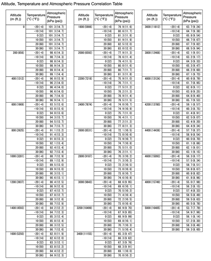
HINT:
- Standard atmospheric pressure is approximately 101 kPa(abs) [15 psi(abs)].
- For every 100 m (328 ft.) increase in altitude, atmospheric pressure drops by approximately 1 kPa (0.1 psi). This varies depending on the weather.
(d) Compare the value of the Data List item Intake Manifold Absolute Pressure with the actual atmospheric pressure.
|
Result | Proceed to |
|---|---|
|
Approximately the same as the actual atmospheric pressure |
A |
| Not approximately the same as the actual atmospheric pressure |
B |
| B |
| REPLACE E.F.I. VACUUM SENSOR ASSEMBLY |
|
| 3. |
READ VALUE USING GTS (ATMOSPHERIC PRESSURE) |
(a) Enter the following menus.
Powertrain > Engine > Data List|
Tester Display |
|---|
| Atmospheric Pressure |
(b) Using the following table, determine the normal atmospheric pressure for the current altitude and temperature.
HINT:
- Standard atmospheric pressure is approximately 101 kPa(abs) [15 psi(abs)].
- For every 100 m (328 ft.) increase in altitude, atmospheric pressure drops by approximately 1 kPa (0.1 psi). This varies depending on the weather.
(c) Compare the value of the Data List item Atmospheric Pressure with the actual atmospheric pressure.
|
Result | Proceed to |
|---|---|
|
Approximately the same as the actual atmospheric pressure |
A |
| Not approximately the same as the actual atmospheric pressure |
B |
| A |
| CHECK FOR INTERMITTENT PROBLEMS |
| B |
| REPLACE ECM |


