Toyota Corolla Cross: Lost Communication with Side Obstacle Detection Control Module "A" (ch2) Missing Message (U117787,U117887)
DESCRIPTION
This DTC is output when the clearance warning ECU assembly detects lost communication with the blind spot monitor sensor.
|
DTC No. |
Detection Item |
DTC Detection Condition |
Trouble Area |
|---|---|---|---|
|
U117787 |
Lost Communication with Side Obstacle Detection Control Module "A" (ch2) Missing Message |
The clearance warning ECU assembly is unable to receive communication from the blind spot monitor sensor RH (A) |
|
|
U117887 |
Lost Communication with Side Obstacle Detection Control Module "B" (ch2) Missing Message |
The clearance warning ECU assembly is unable to receive communication from the blind spot monitor sensor LH (B) |
|
WIRING DIAGRAM

CAUTION / NOTICE / HINT
NOTICE:
- Inspect the fuses for circuits related to this system before performing the following procedure.
- Before measuring the resistance of the CAN bus, turn the ignition switch off and leave the vehicle for 1 minute or more without operating the key or any switches, or opening or closing the doors. After that, disconnect the cable from the negative (-) battery terminal and leave the vehicle for 1 minute or more before measuring the resistance.
- After turning the ignition switch off, waiting time may be required
before disconnecting the cable from the negative (-) battery terminal. Therefore,
make sure to read the disconnecting the cable from the negative (-) battery
terminal notices before proceeding with work.
Click here
.gif)
HINT:
- Operating the ignition switch, any other switches or a door triggers related ECU and sensor communication on the CAN. This communication will cause the resistance value to change.
- Even after DTCs are cleared, if a DTC is stored again after driving the vehicle for a while, the malfunction may be occurring due to vibration of the vehicle. In such a case, wiggling the ECUs or wire harness while performing the inspection below may help determine the cause of the malfunction.
PROCEDURE
|
1. |
CLEAR DTC |
(a) Clear the DTCs.
Body Electrical > Clearance Warning > Clear DTCs
|
.gif)
|
2. |
CHECK FOR DTC |
(a) Check for DTCs.
Body Electrical > Clearance Warning > Trouble Codes|
Result |
Proceed to |
|---|---|
|
Only U117787 is output |
A |
|
Only U117887 is output |
B |
|
U117787 and U117887 are output |
C |
|
None of the above conditions are met |
D |
| B | .gif)
|
GO TO STEP 5 |
| C |
|
GO TO STEP 7 |
| D |
|
USE SIMULATION METHOD TO CHECK |
|
|
3. |
CHECK HARNESS AND CONNECTOR (BLIND SPOT MONITOR SENSOR RH (A) - BATTERY AND BODY GROUND) |
(a) Disconnect the S13 blind spot monitor sensor RH (A) connector.
(b) Measure the resistance according to the value(s) in the table below.
Standard Resistance:
|
Tester Connection |
Condition |
Specified Condition |
|---|---|---|
|
S13-10 (BRGD) - Body ground |
Always |
Below 1 Ω |
| NG |
|
REPAIR OR REPLACE HARNESS OR CONNECTOR |
|
|
4. |
CHECK HARNESS AND CONNECTOR (BLIND SPOT MONITOR SENSOR RH (A) - BATTERY AND BODY GROUND) |
(a) Disconnect the S13 blind spot monitor sensor RH (A) connector.
(b) Measure the voltage according to the value(s) in the table below.
Standard Voltage:
|
Tester Connection |
Switch Condition |
Specified Condition |
|---|---|---|
|
S13-5 (BRB) - Body ground |
Ignition switch ON |
11 to 14 V |
|
S13-5 (BRB) - Body ground |
Ignition switch off |
Below 1 V |
| OK |
|
REPLACE BLIND SPOT MONITOR SENSOR RH (A) |
| NG |
|
REPAIR OR REPLACE HARNESS OR CONNECTOR |
|
5. |
CHECK HARNESS AND CONNECTOR (BLIND SPOT MONITOR SENSOR LH (B) - BATTERY AND BODY GROUND) |
(a) Disconnect the S12 blind spot monitor sensor LH (B) connector.
(b) Measure the resistance according to the value(s) in the table below.
Standard Resistance:
|
Tester Connection |
Condition |
Specified Condition |
|---|---|---|
|
S12-10 (BLGD) - Body ground |
Always |
Below 1 Ω |
| NG |
|
REPAIR OR REPLACE HARNESS OR CONNECTOR |
|
|
6. |
CHECK HARNESS AND CONNECTOR (BLIND SPOT MONITOR SENSOR LH (B) - BATTERY AND BODY GROUND) |
(a) Disconnect the S12 blind spot monitor sensor LH (B) connector.
(b) Measure the voltage according to the value(s) in the table below.
Standard Voltage:
|
Tester Connection |
Switch Condition |
Specified Condition |
|---|---|---|
|
S12-5 (BLB) - Body ground |
Ignition switch ON |
11 to 14 V |
|
S12-5 (BLB) - Body ground |
Ignition switch off |
Below 1 V |
| OK |
|
REPLACE BLIND SPOT MONITOR SENSOR LH (B) |
| NG |
|
REPAIR OR REPLACE HARNESS OR CONNECTOR |
|
7. |
CHECK CAN BUS MAIN WIRE |
(a) Turn the ignition switch off.
(b) Disconnect the cable from the negative (-) auxiliary battery terminal.
|
(c) Measure the resistance according to the value(s) in the table below. Standard Resistance:
|
|
|
Result |
Proceed to |
|---|---|
|
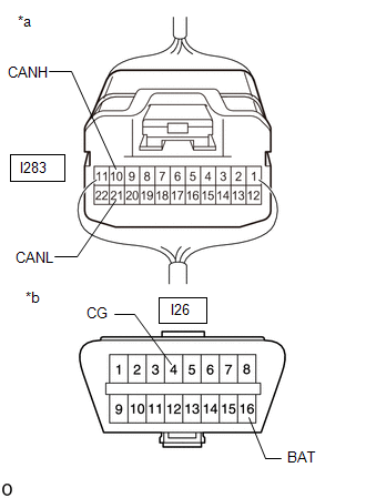
I283-10 (CANH) - I283-21 (CANL) is more than or equal to 70 Ω |
A |
|
I283-10 (CANH) - I283-21 (CANL) is less than or equal to 54 Ω |
B |
|
I283-10 (CANH) - I26-4 (CG) is less than or equal to 200 Ω |
C |
|
I283-21 (CANL) - I26-4 (CG) is less than or equal to 200 Ω |
D |
|
I283-10 (CANH) - I26-16 (BAT) is less than or equal to 6 kΩ |
E |
|
I283-21 (CANL) - I26-16 (BAT) is less than or equal to 6 kΩ |
F |
|
None of the above conditions are met |
G |
| B |
|
GO TO STEP 14 |
| C |
|
GO TO STEP 20 |
| D |
|
GO TO STEP 20 |
| E |
|
GO TO STEP 20 |
| F |
|
GO TO STEP 20 |
| G |
|
GO TO STEP 26 |
|
|
8. |
CHECK FOR OPEN IN CAN BUS WIRE (NO. 4 CAN JUNCTION CONNECTOR) |
(a) Disconnect the I283 No. 4 CAN junction connector.
(b) Measure the resistance according to the value(s) in the table below.
Standard Resistance:
|
Tester Connection |
Condition |
Specified Condition |
|---|---|---|
|
I283-11 (CANH) - I283-22 (CANL) |
Cable disconnected from negative (-) battery terminal |
108 to 132 Ω |
| NG |
|
GO TO STEP 13 |
|
|
9. |
CHECK FOR OPEN IN CAN BUS WIRE (NO. 4 CAN JUNCTION CONNECTOR) |
(a) Disconnect the I283 No. 4 CAN junction connector.
(b) Measure the resistance according to the value(s) in the table below.
Standard Resistance:
|
Tester Connection |
Condition |
Specified Condition |
|---|---|---|
|
I283-9 (CANH) - I283-20 (CANL) |
Cable disconnected from negative (-) battery terminal |
108 to 132 Ω |
| NG |
|
GO TO STEP 12 |
|
|
10. |
CHECK FOR OPEN IN CAN BUS WIRE (NO. 4 CAN JUNCTION CONNECTOR) |
(a) Disconnect the I283 No. 4 CAN junction connector.
(b) Measure the resistance according to the value(s) in the table below.
Standard Resistance:
|
Tester Connection |
Condition |
Specified Condition |
|---|---|---|
|
I283-10 (CANH) - I283-21 (CANL) |
Cable disconnected from negative (-) battery terminal |
200 Ω or higher |
| OK |
|
REPLACE NO. 4 CAN JUNCTION CONNECTOR |
|
|
11. |
CHECK FOR OPEN IN CAN BUS WIRE (CLEARANCE WARNING ECU ASSEMBLY) |
(a) Reconnect the I283 No. 4 CAN junction connector.
(b) Disconnect the I24 clearance warning ECU connector.
(c) Measure the resistance according to the value(s) in the table below.
Standard Resistance:
|
Tester Connection |
Condition |
Specified Condition |
|---|---|---|
|
I24-37 (CANH) - I24-38 (CANL) |
Cable disconnected from negative (-) battery terminal |
54 to 69 Ω |
| OK |
|
REPLACE CLEARANCE WARNING ECU ASSEMBLY |
| NG |
|
REPAIR OR REPLACE CAN BUS WIRE (CLEARANCE WARNING ECU ASSEMBLY - NO. 4 CAN JUNCTION CONNECTOR) |
|
12. |
CHECK FOR OPEN IN CAN BUS MAIN WIRE (BLIND SPOT MONITOR SENSOR RH (A)) |
(a) Reconnect the I283 No. 4 CAN junction connector.
(b) Disconnect the S13 blind spot monitor sensor RH (A) connector.
(c) Measure the resistance according to the value(s) in the table below.
Standard Resistance:
|
Tester Connection |
Condition |
Specified Condition |
|---|---|---|
|
S13-1 (CA2P) - S13-6 (CA2N) |
Cable disconnected from negative (-) battery terminal |
108 to 132 Ω |
| OK |
|
REPLACE BLIND SPOT MONITOR SENSOR RH (A) |
| NG |
|
REPAIR OR REPLACE CAN MAIN WIRE OR CONNECTOR (BLIND SPOT MONITOR SENSOR RH (A) - NO. 4 CAN JUNCTION CONNECTOR) |
|
13. |
CHECK FOR OPEN IN CAN BUS MAIN WIRE (BLIND SPOT MONITOR SENSOR LH (B)) |
(a) Reconnect the I283 No. 4 CAN junction connector.
(b) Disconnect the S12 blind spot monitor sensor LH (B) connector.
(c) Measure the resistance according to the value(s) in the table below.
Standard Resistance:
|
Tester Connection |
Condition |
Specified Condition |
|---|---|---|
|
S12-1 (CA2P) - S12-6 (CA2N) |
Cable disconnected from negative (-) battery terminal |
108 to 132 Ω |
| OK |
|
REPLACE BLIND SPOT MONITOR SENSOR LH (B) |
| NG |
|
REPAIR OR REPLACE CAN MAIN WIRE OR CONNECTOR (BLIND SPOT MONITOR SENSOR LH (B) - NO. 4 CAN JUNCTION CONNECTOR) |
|
14. |
CHECK FOR SHORT IN CAN BUS WIRES (NO. 4 CAN JUNCTION CONNECTOR) |
(a) Disconnect the I283 No. 4 CAN junction connector.
(b) Measure the resistance according to the value(s) in the table below.
Standard Resistance:
|
Tester Connection |
Condition |
Specified Condition |
|---|---|---|
|
I283-11 (CANH) - I283-22 (CANL) |
Cable disconnected from negative (-) battery terminal |
108 to 132 Ω |
| NG |
|
GO TO STEP 19 |
|
|
15. |
CHECK FOR SHORT IN CAN BUS WIRES (NO. 4 CAN JUNCTION CONNECTOR) |
(a) Disconnect the I283 No. 4 CAN junction connector.
(b) Measure the resistance according to the value(s) in the table below.
Standard Resistance:
|
Tester Connection |
Condition |
Specified Condition |
|---|---|---|
|
I283-9 (CANH) - I283-20 (CANL) |
Cable disconnected from negative (-) battery terminal |
108 to 132 Ω |
| NG |
|
GO TO STEP 18 |
|
|
16. |
CHECK FOR SHORT IN CAN BUS WIRES (NO. 4 CAN JUNCTION CONNECTOR) |
(a) Disconnect the I283 No. 4 CAN junction connector.
(b) Measure the resistance according to the value(s) in the table below.
Standard Resistance:
|
Tester Connection |
Condition |
Specified Condition |
|---|---|---|
|
I283-10 (CANH) - I283-21 (CANL) |
Cable disconnected from negative (-) battery terminal |
200 Ω or higher |
| OK |
|
REPLACE NO. 4 CAN JUNCTION CONNECTOR |
|
|
17. |
CHECK FOR SHORT IN CAN BUS WIRES (CLEARANCE WARNING ECU ASSEMBLY) |
(a) Reconnect the I283 No. 4 CAN junction connector.
(b) Disconnect the I24 clearance warning ECU connector.
(c) Measure the resistance according to the value(s) in the table below.
Standard Resistance:
|
Tester Connection |
Condition |
Specified Condition |
|---|---|---|
|
I24-37 (CANH) - I24-38 (CANL) |
Cable disconnected from negative (-) battery terminal |
54 to 69 Ω |
| OK |
|
REPLACE CLEARANCE WARNING ECU ASSEMBLY |
| NG |
|
REPAIR OR REPLACE CAN BUS WIRE (CLEARANCE WARNING ECU ASSEMBLY - NO. 4 CAN JUNCTION CONNECTOR) |
|
18. |
CHECK FOR SHORT IN CAN BUS WIRES (BLIND SPOT MONITOR SENSOR RH (A)) |
(a) Reconnect the I283 No. 4 CAN junction connector.
(b) Disconnect the S13 blind spot monitor sensor RH (A) connector.
(c) Measure the resistance according to the value(s) in the table below.
Standard Resistance:
|
Tester Connection |
Condition |
Specified Condition |
|---|---|---|
|
S13-1 (CA2P) - S13-6 (CA2N) |
Cable disconnected from negative (-) battery terminal |
108 to 132 Ω |
| OK |
|
REPLACE BLIND SPOT MONITOR SENSOR RH (A) |
| NG |
|
REPAIR OR REPLACE CAN MAIN WIRE OR CONNECTOR (BLIND SPOT MONITOR SENSOR RH (A) - NO. 4 CAN JUNCTION CONNECTOR) |
|
19. |
CHECK FOR SHORT IN CAN BUS WIRES (BLIND SPOT MONITOR SENSOR LH (B)) |
(a) Reconnect the I283 No. 4 CAN junction connector.
(b) Disconnect the S12 blind spot monitor sensor LH (B) connector.
(c) Measure the resistance according to the value(s) in the table below.
Standard Resistance:
|
Tester Connection |
Condition |
Specified Condition |
|---|---|---|
|
S12-1 (CA2P) - S12-6 (CA2N) |
Cable disconnected from negative (-) battery terminal |
108 to 132 Ω |
| OK |
|
REPLACE BLIND SPOT MONITOR SENSOR LH (B) |
| NG |
|
REPAIR OR REPLACE CAN MAIN WIRE OR CONNECTOR (BLIND SPOT MONITOR SENSOR LH (B) - NO. 4 CAN JUNCTION CONNECTOR) |
|
20. |
CHECK FOR SHORT IN CAN BUS WIRES (NO. 4 CAN JUNCTION CONNECTOR) |
(a) Disconnect the I283 No. 4 CAN junction connector.
(b) Measure the resistance according to the value(s) in the table below.
Standard Resistance:
|
Tester Connection |
Condition |
Specified Condition |
|---|---|---|
|
I283-10 (CANH) - I26-4 (CG) |
Cable disconnected from negative (-) battery terminal |
200 Ω or higher |
|
I283-21 (CANL) - I26-4 (CG) |
Cable disconnected from negative (-) battery terminal |
200 Ω or higher |
|
I283-10 (CANH) - I26-16 (BAT) |
Cable disconnected from negative (-) battery terminal |
6 kΩ or higher |
|
I283-21 (CANL) - I26-16 (BAT) |
Cable disconnected from negative (-) battery terminal |
6 kΩ or higher |
HINT:
Check for short that was confirmed to be a malfunction by confirming symptoms.
| NG |
|
GO TO STEP 25 |
|
|
21. |
CHECK FOR SHORT IN CAN BUS WIRES (NO. 4 CAN JUNCTION CONNECTOR) |
(a) Disconnect the I283 No. 4 CAN junction connector.
(b) Measure the resistance according to the value(s) in the table below.
Standard Resistance:
|
Tester Connection |
Condition |
Specified Condition |
|---|---|---|
|
I283-9 (CANH) - I26-4 (CG) |
Cable disconnected from negative (-) battery terminal |
200 Ω or higher |
|
I283-20 (CANL) - I26-4 (CG) |
Cable disconnected from negative (-) battery terminal |
200 Ω or higher |
|
I283-9 (CANH) - I26-16 (BAT) |
Cable disconnected from negative (-) battery terminal |
6 kΩ or higher |
|
I283-20 (CANL) - I26-16 (BAT) |
Cable disconnected from negative (-) battery terminal |
6 kΩ or higher |
HINT:
Check for short that was confirmed to be a malfunction by confirming symptoms.
| NG |
|
GO TO STEP 24 |
|
|
22. |
CHECK FOR SHORT IN CAN BUS WIRES (NO. 4 CAN JUNCTION CONNECTOR) |
(a) Disconnect the I283 No. 4 CAN junction connector.
(b) Measure the resistance according to the value(s) in the table below.
Standard Resistance:
|
Tester Connection |
Condition |
Specified Condition |
|---|---|---|
|
I283-11 (CANH) - I26-4 (CG) |
Cable disconnected from negative (-) battery terminal |
200 Ω or higher |
|
I283-22 (CANL) - I26-4 (CG) |
Cable disconnected from negative (-) battery terminal |
200 Ω or higher |
|
I283-11 (CANH) - I26-16 (BAT) |
Cable disconnected from negative (-) battery terminal |
6 kΩ or higher |
|
I283-22 (CANL) - I26-16 (BAT) |
Cable disconnected from negative (-) battery terminal |
6 kΩ or higher |
HINT:
Check for short that was confirmed to be a malfunction by confirming symptoms.
| OK |
|
REPLACE NO. 4 CAN JUNCTION CONNECTOR |
|
|
23. |
CHECK FOR SHORT IN CAN BUS WIRES (BLIND SPOT MONITOR SENSOR LH (B)) |
(a) Reconnect the I283 No. 4 CAN junction connector.
(b) Disconnect the S12 blind spot monitor sensor LH (B) connector.
(c) Measure the resistance according to the value(s) in the table below.
Standard Resistance:
|
Tester Connection |
Condition |
Specified Condition |
|---|---|---|
|
S12-1 (CA2P) - I26-4 (CG) |
Cable disconnected from negative (-) battery terminal |
200 Ω or higher |
|
S12-6 (CA2N) - I26-4 (CG) |
Cable disconnected from negative (-) battery terminal |
200 Ω or higher |
|
S12-1 (CA2P) - I26-16 (BAT) |
Cable disconnected from negative (-) battery terminal |
6 kΩ or higher |
|
S12-6 (CA2N) - I26-16 (BAT) |
Cable disconnected from negative (-) battery terminal |
6 kΩ or higher |
| OK |
|
REPLACE BLIND SPOT MONITOR SENSOR LH (B) |
| NG |
|
REPAIR OR REPLACE CAN MAIN WIRE OR CONNECTOR (BLIND SPOT MONITOR SENSOR LH (B) - NO. 4 CAN JUNCTION CONNECTOR) |
|
24. |
CHECK FOR SHORT IN CAN BUS WIRES (BLIND SPOT MONITOR SENSOR RH (A)) |
(a) Reconnect the I283 No. 4 CAN junction connector.
(b) Disconnect the S13 blind spot monitor sensor RH (A) connector.
(c) Measure the resistance according to the value(s) in the table below.
Standard Resistance:
|
Tester Connection |
Condition |
Specified Condition |
|---|---|---|
|
S13-1 (CA2P) - I26-4 (CG) |
Cable disconnected from negative (-) battery terminal |
200 Ω or higher |
|
S13-6 (CA2N) - I26-4 (CG) |
Cable disconnected from negative (-) battery terminal |
200 Ω or higher |
|
S13-1 (CA2P) - I26-16 (BAT) |
Cable disconnected from negative (-) battery terminal |
6 kΩ or higher |
|
S13-6 (CA2N) - I26-16 (BAT) |
Cable disconnected from negative (-) battery terminal |
6 kΩ or higher |
| OK |
|
REPLACE BLIND SPOT MONITOR SENSOR RH (A) |
| NG |
|
REPAIR OR REPLACE CAN MAIN WIRE OR CONNECTOR (BLIND SPOT MONITOR SENSOR RH (A) - NO. 4 CAN JUNCTION CONNECTOR) |
|
25. |
CHECK FOR SHORT IN CAN BUS WIRES (CLEARANCE WARNING ECU ASSEMBLY) |
(a) Reconnect the I283 No. 4 CAN junction connector.
(b) Disconnect the I24 clearance warning ECU connector.
(c) Measure the resistance according to the value(s) in the table below.
Standard Resistance:
|
Tester Connection |
Condition |
Specified Condition |
|---|---|---|
|
I24-37 (CANH) - I26-4 (CG) |
Cable disconnected from negative (-) battery terminal |
200 Ω or higher |
|
I24-38 (CANL) - I26-4 (CG) |
Cable disconnected from negative (-) battery terminal |
200 Ω or higher |
|
I24-37 (CANH) - I26-16 (BAT) |
Cable disconnected from negative (-) battery terminal |
6 kΩ or higher |
|
I24-38 (CANL) - I26-16 (BAT) |
Cable disconnected from negative (-) battery terminal |
6 kΩ or higher |
| OK |
|
REPLACE CLEARANCE WARNING ECU ASSEMBLY |
| NG |
|
REPAIR OR REPLACE CAN BUS WIRE (CLEARANCE WARNING ECU ASSEMBLY - NO. 4 CAN JUNCTION CONNECTOR) |
|
26. |
CHECK CLEAR DTCS |
(a) Using the GTS, clear the DTCs.
Body Electrical > Clearance Warning > Clear DTCs
|
|
27. |
CHECK FOR DTC |
(a) Check for DTCs.
Body Electrical > Clearance Warning > Trouble Codes|
Result |
Proceed to |
|---|---|
|
U117787 and U117887 are output |
A |
|
U117787 and U117887 are not output |
B |
| A |
|
REPLACE CLEARANCE WARNING ECU ASSEMBLY |
| B |
|
GO TO PROBLEM SYMPTOM SIMULATION METHOD |
READ NEXT:
 Precaution
PRECAUTION
NOTES FOR TELEVISION CAMERA ASSEMBLY
(a) Notes for the television camera assembly
(1) The rear view monitor system may not function properly if subjected
to a severe blow by any hard o
Parts Location
PARTS LOCATION
ILLUSTRATION
*1
REAR TELEVISION CAMERA ASSEMBLY
-
-
ILLUSTRATION
*1
RADIO AND DISPLAY RECEIVER ASSEMBL
SEE MORE:
 Removal
REMOVAL CAUTION / NOTICE / HINT COMPONENTS (REMOVAL)
Procedure Part Name Code
1 CUT KEY
69503B
- -
2 TRANSMITTER HOUSING COVER
-
- -
3 TRANSMITTER BATTERY
89745C
- -
Removal
REMOVAL CAUTION / NOTICE / HINT COMPONENTS (REMOVAL)
Procedure Part Name Code
1 FRONT FLOOR CENTER BRACE
57533B -
- -
2 FRONT EXHAUST PIPE ASSEMBLY (TWC: Rear Catalyst)
17410
- -
3 PROPELLER SHAFT WITH
